EasyManua.ls Logo

Murphy Pull/Push DC Solenoids RP2307B User Manual

Murphy Pull/Push DC Solenoids RP2307B
4 pages
To Next Page IconTo Next Page
Page #1 background imageLoading...
Page #1 background image
RPS-00092B page 1 of 4
MODEL & PART NUMBERS: DC SOLENOIDS & ACCESSORIES SHIPPING WEIGHT
Model No. Description ozs (kg)
RP2307B 12 VDC, 1 in. (25 mm) stroke, 11 lbf (49 N) pull, 23 lbf (102 N) hold 24 ozs (0.7 kg)
RP2308B 24 VDC, 1 in. (25 mm) stroke, 11 lbf (49 N) pull, 23 lbf (102 N) hold 24 ozs (0.7 kg)
RP2309B 12 VDC, 1-1/2 in. (38 mm) stroke, 14 lbf (62 N) pull, 34 lbf (151 N) hold 48 ozs (1.4 kg)
RP2310B 24VDC, 1-1/2 in. (38 mm) stroke, 14 lbf (62 N) pull, 34 lbf (151 N) hold 48 ozs (1.4 kg)
65-01-0108 Clevis yoke assembly 1 ozs (.03 kg)
65-01-0110 Clevis yoke chain assembly 2 ozs (.04 kg)
40-05-0315 Threaded rod (1-1/2 in.) .05 ozs (.001 kg)
00-00-2457 RPS in-line ball joint .05 ozs (.001 kg)
00-00-2458 RPS 90° ball joint 1 ozs (.03 kg)
RP Series
One Solenoid For Pull/Push Operation
No Internal Switches
Reduce Coil Burnout
Boost Reliability
Reduce Adjustments
High Force–Small Size
Can Be Used With Most Engines
Start Systems
SD85 Solenoid Drive Time Delay
Available To Greatly Reduce Possibility
Of Coil Burnout And Facilitate Low
Current Piloted Operation.
RP2307B & RP2308B
RP2309B & RP2310B
RPS-00092B
Revised 11-03
Catalog Section 40
(00-02-0107)
Pull/Push DC Solenoids for
Diesel Engines
Description
Murphy push/pull DC Solenoids
provide single unit versatility for engine
applications, such as shutdown.
A choice of two models and two
voltages is available. All models come
complete with return spring and rubber
seal boot. See the next page for
specifications and options.
Basic Models
Models RP2307B and RP2308B give a
full one inch (25 mm) stroke at 11
pounds (49 N) and hold up to 23 pounds
(102 N) at full voltage, continuous duty.
They will operate at any stroke less than
maximum; refer to the chart shown on
page 2.
Models RP2309B and RP2310B can
pull 14 pounds (62 N) with a one-and-a-
half inch (38 mm) stroke. They hold up
to 34 pounds (151 N) at full voltage,
continuous duty. See the chart on page 2
for holding force at any stroke less than
maximum.
SD85 Solenoid Drive
Time Delay
Using the SD85 ensures the energize
coil is only powered for 1-2 seconds
with each operation. If the plunger does
not seat in that time, it is highly
unlikely it will seat. The hold coil is
energized as long as the signal to the
SD85 is active. This insures long life of
the RP solenoid.
Warranty
A limited warranty on materials and workmanship
is given with this FW Murphy product. A copy of
the warranty may be viewed or printed by going
to www
.fwmurphy.com/support/warranty.htm
Question and Answer IconNeed help?

Do you have a question about the Murphy Pull/Push DC Solenoids RP2307B and is the answer not in the manual?

Murphy Pull/Push DC Solenoids RP2307B Specifications

General IconGeneral
BrandMurphy
ModelPull/Push DC Solenoids RP2307B
CategoryAutomobile Parts
LanguageEnglish

Summary

RP Series

RP Series Features

Highlights key advantages of RP Series solenoids for engine applications, including high force and small size.

SD85 Solenoid Drive Time Delay

SD85 Description and Benefits

Details the SD85's function in reducing coil burnout and facilitating low current piloted operation.

Product Description

Basic Models RP2307B/RP2308B

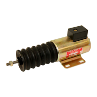
Specifies stroke and holding force for RP2307B and RP2308B models at full voltage.

Solenoid Dimensions

RP2307B and RP2308B Dimensions

Provides detailed dimensional drawings for RP2307B and RP2308B solenoids.

RP2309B and RP2310B Dimensions

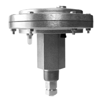
Provides detailed dimensional drawings for RP2309B and RP2310B solenoids.

Wiring Diagrams

Time-Delayed Shutdown with 518PH Switch

Illustrates typical wiring for time-delayed shutdown using a 518PH magnetic switch.

Time-Delayed Shutdown with 760A Switch

Illustrates typical wiring for time-delayed shutdown using a 760A magnetic switch.

Mechanical Installation

Installation Guidelines

Provides essential steps for securely mounting the solenoid and connecting linkages.

Electrical Installation

Wiring Recommendations

Specifies wire size and length requirements for proper electrical connection.

Operation

Solenoid Operation and Precautions

Explains solenoid coil energization during engine start and run modes with safety notes.

Linkage Parts and Assemblies

Accessory Components

Lists and illustrates available linkage parts like rods, ball joints, and yoke assemblies.

SD85 Terminal Block

SD85 Terminal Connections

Details the terminal layout and wiring for the SD85 Solenoid Drive Time Delay.