24
TO LEVEL MOWER
Make sure tires are properly inflated to
the PSI shown on tires. If tires are over
or under inflated, it may affect the appear-
ance of your lawn and lead you to think
the mower is not adjusted properly.
VISUAL SIDE-TO-SIDE ADJUSTMENT
1. With all tires properly inflated and if
your lawn appears unevenly cut, de-
termine which side of mower is cutting
lower.
NOTE: As desired, you can raise the low
side of mower or lower the high side.
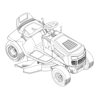
2. Go to side of mower you wish to adjust.
3. With a 3/4" or adjustable wrench, turn
lift link adjustment nut (A) to the left
to lower the mower, or, to the right to
raise the mower.
02966
A
A
02548
B
B
NOTE: Each full turn of adjustment nut will
change mower height about 3/16".
4. Test your adjustment by mowing some
uncut grass and visually checking the
appearance. Readjust, if necessary,
until you are satisfied with the results.
PRECISION SIDE-TO-SIDE
ADJUSTMENT
1. With all tires properly inflated, park
tractor on level ground or driveway.
CAUTION: Blades are sharp. Protect
your hands with gloves and/or wrap blade
with heavy cloth.
2. Raise mower to its highest position.
3. At both sides of mower, position blade
at side and measure the distance
(A) from bottom edge of blade to the
ground. The distance should be the
same on both sides.
4. If adjustment is necessary, see steps 2
and 3 in Visual Adjustment instructions
above.
5. Recheck measurements, adjust if nec-
essary until both sides are equal.
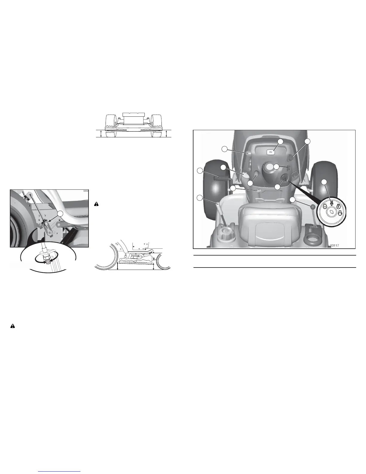
FRONT-TO-BACK ADJUSTMENT
IMPORTANT: Deck must be level side-
to-side.
To obtain the best cutting re sults, the
mower blades should be adjusted so the
front tip is 1/8" to 1/2" lower than the rear
tip when the mower is in its highest posi-
tion.
CAUTION: Blades are sharp. Protect
your hands with gloves and/or wrap blade
with heavy cloth.
• Raise mower to highest position.
• Position any blade so the tip is pointing
straight forward. Measure distance (B)
to the ground at front and rear tip of the
blade.
• If front tip of blade is not 1/8" to 1/2"
lower than the rear tip, go to the front of
tractor.
• With an 11/16" or adjustable wrench,
loosen jam nut A several turns to clear
adjustment nut B.
• With a 3/4" or adjustable wrench, turn
front link adjustment nut (B) clockwise
(tighten) to raise the front of mower, or,
counterclockwise (loosen) to lower the
front mower.
A
Turn nut left
to lower mower
Turn nut right
to raise mower
45
Nuestros tractores cumplen con los estándares de seguridad del
American National Standard Institute.
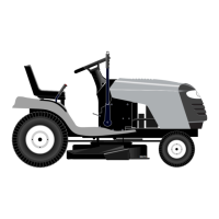
(A) PALANCA DEL LEVANTAMIENTO DEL
ACCESORIO – Se usa para levantar, bajar y
ajustar el conjunto segador o los demás ac ce so-
rios montados en su tractor.
(B) PEDAL DEL EMBRAGUE/FRENO – Se
usa para desembragar y frenar el tractor y para
hacer arrancar el motor.
(C) PEDAL DEL EMBRAGUE/FRENO – Se
usa para desembragar y frenar el tractor y para
hacer arrancar el mo tor.
(D) CONTROL DE ACELERACIÓN – Se usa
para controlar la ve lo ci dad del motor.
(E) INTERRUPTOR DEL EMBRAGUE DEL
ACCESORIO – Se usa para enganchar las
cuchillas segadoras, o los demás ac ce so rios
montados en su tractor.
(F) INTERRUPTOR DE IGNICIÓN – Se usa
para hacer arrancar o hacer parar el motor.
(G) SISTEMA DE FUNCIONAMIENTO HACIA
ATRÁS (ROS) en posición “ON” – Permite la
operación del conjunto segador o otro acceso-
rio accionado mientras que en revés.
(H) INTERRUPTOR DE LA LUZ – Enciende y
apaga las luces de lan te ras.
(J) PALANCA DE CAMBIO – Selecciona la
velocidad y la di rec ción del tractor.
(N) CONTROL DE ESTRANGULACIÓN – Se
usa cuando se hace arrancar un motor frío.
(P) DISPOSITIVO DE AVISO DE SERVICIO /
CRONÓMETRO – Indica cuándo hay que hac-
erles el servicio al motor y a la cortadora.
(Q) PUERTO DE LA ENGERGIA 12 VOLT – Se
usa para los accesorios 12-volt.
FAMILIARICESE CON SU TRACTOR
LEA ESTE MANUAL DEL DUEÑO Y LAS REGLAS DE SEGURIDAD ANTES DE OPERAR
SU TRACTOR
Compare las ilustraciones con su tractor para familiarizarse con las ubicaciones de los diversos
controles y ajustes. Guarde este manual para referencia en el futuro.
E
F
C
P
D
G
H
Q
C
B
N
J