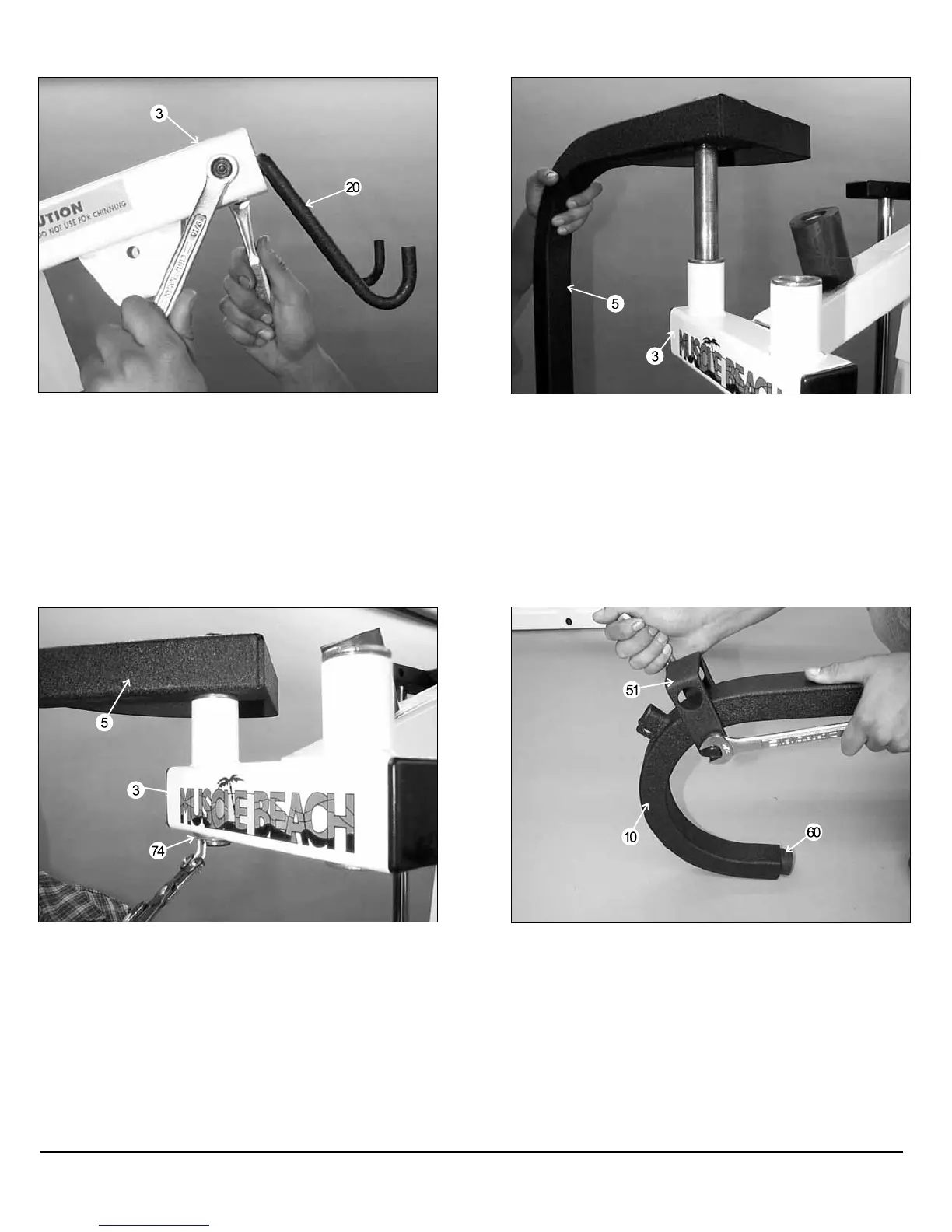
FIG. 17 Insert the Lat Bar Holder (#20) into the tube-end of
the Top Pulley Assembly (#3), as shown above, and secure
using one Hex Head Cap Screw 3/8-16 X 2 1/2 (#56), two Flat
Washers SAE 3/8 (#73) and one Nylon Insert Jam Lock Nut
3/8-16 (#69).
FIG. 18 Insert both Pec Dec Arms (#5) and (#4-Not
Shown) into the receptacle tube on the Top Pulley Assembly
(#3), as shown. Note: It is recommended that the axles on both
Pec Dec Arms (#5) and (#4-Not Shown) be lubricated with
grease prior to the assembly.
FIG. 19 Secure both Pec Dec Arms (#5) and (#4-Not
Shown) to the Top Pulley Assembly (#3) using two Retaining
Snap Rings (#74). If possible, use special snap ring pliers for
this job, as shown above. If not available, carefully work each
Retaining Snap Ring (#74) into the groove, then push down
alternately with a screw driver working the Retaining Snap Ring
(#74) into the groove. Note: Be careful not to distort the
Retaining Snap Ring (#74) or bend it.
FIG. 20 Now attach the Foot Roll Bracket (#51) to the Leg
Ext Arm (#10) and secure it using one Hex Head Cap Screw
1/2-13 X 2 3/4 (#86), two Flat Washers SAE 1/2 (#72) and one
Nylon Insert Jam Lock Nut 3/8-16 (#71). Next, install a Rubber
Bumper 3/8 X 1 1/2 (#60) to the Leg Ext Arm (#10), as shown,
using one Hex Head Cap Screw 3/8-16 X 1 (#59) and one Flat
Washer SAE 3/8 (#73). Note: Do not over-tighten this bolt as
the Foot Roll Bracket (#51) should be allowed to swivel
freely.
Owners’ Manual: Assembly Instructions
CMB-2 Muscle Beach Home Gym
6


 To Next Page
 Loading...
