PRINTED IN U.S.A. 45 913229/CP0615
Internal service on any of these components should
only be performed by (or under the direction of) an
authorized Mustang Telehandler dealer.
WARNING
Tilt, lift, extend and leveling cylinders have
counterbalance valves. These valves keep
hydraulic fluid from entering and exiting the
cylinders while they are not being activated,
and they are under extremely high pressure.
Before removing one of these valves, you
ARE REQUIRED to call your Mustang dealer
or Mustang Manufacturing Company Service
Department. Failure to do so may result in
serious injury or death.
ELECTRICAL COMPONENTS
An electrical system schematic is provided, which
includes instrumentation, electrical components and
switch connections. It is located at the back of this
manual and can be used as a guide for service refer-
ence, as required.
OPERATOR SERVICES
Some of the operator-related services will require
access to components located inside the superstructure,
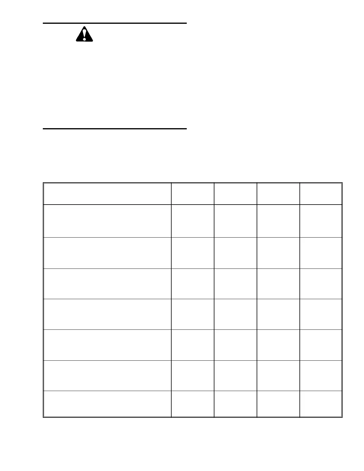
under shields, hoods and covers. The chart on this page
notes the components accessed in each particular area.
Component Operator’s Frame Front Mid-Rear
Station Cover Hood
Axle (underside) z
Engine z
Transmission (center area) z
Drive Shafts (underside) z
Main Control Valve (rear) z
Muffler (underside) z
Air Cleaner (top fuel tank) z
Battery z
Radiator z
Brake Valve (underside) z
Travel Controls (dash area) z
Boom Controls (right side) z
Hydraulic Test Ports z
Hourmeter (dash) z
Switches/Indicators (dash) z
Hydraulic Pump z
Hydraulic Filter (Reservoir) z
Misc. Hydraulic Valves z
Heater (lower front) z
ACCESS TO COMPONENTS CHART


 To Next Page