4096-702
PRODELIN CORPORATION Small Aperture Universal Mount
_____________________________________________________________________________
3
Trimast Installation Instructions
Tri-mast Assembly
1. Determine installation site. (vertical surface (wall), horizontal surface (ground), or
sloped surface)
2. There are two assembly configurations for the trimast. If the installation site is a wall
or ground, then the factory assembly configuration (“Configuration 1” of Figure 1) is
correct. Also if the installation site is a sloped surface up to 30° or greater than 55°
with 16” on center rafters or greater than 60° with 24” on center rafters, then the
factory assembly configuration is correct. Refer to Figure 1 for details.
3. If the installation site is a sloped surface not identified above, the trimast assembly
must be reconfigured to “Configuration 2” in Figure 1.
4. To do this, remove the (2) carriage bolts, flatwashers, and nuts holding the base
bracket to the mast pipe. Locate the base bracket on the opposite end of the mast pipe
and re-attach using the same hardware.
5. Next, remove the carriage bolt, flatwasher, and nut holding the (2) adjustable legs to
the mast pipe. Relocate the (2) legs to the opposite end of the mast pipe and re-attach
using the same hardware.
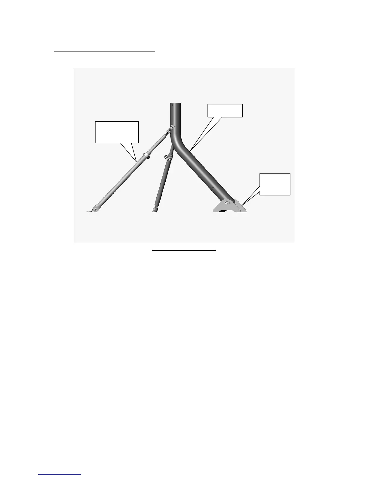
Mast Pipe
Adjustable
Leg (2)
Base
Bracket