Do you have a question about the MW MOUNTS Extra Large Full Motion MW150C75 and is the answer not in the manual?
Maximum loading weight is 150 lbs. Exceeding may cause instability and injury.
Information about product accuracy, completeness, and warranty is provided. User responsibility for installation is stated.
Failure to follow instructions can lead to serious injury, property damage, or warranty voidance.
Lists all hardware components with their respective product numbers and quantities.
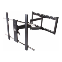
Identifies the main physical components of the mount system, labeled A, B, and C.
Details on how to install the mount in a corner location, including wall placement considerations.
Attaching the monitor plate to the TV, with options for flat and curved backs.
Centering the plate and securing vertical rails to the monitor plate.
Instructions for marking pilot holes for wood stud or concrete installation.
Drilling pilot holes and mounting the wall plate for wood stud or concrete installation.
Allows for lateral adjustment of the arm assembly to center the TV, if necessary.
Connecting the universal mount bracket to the arm assembly and wall bracket.
Fastening the monitor plate to the arm assembly using acorn nuts and washers.
Adjusting the tilt mechanism tension and using the built-in level for post-installation correction.
| Mount Type | Full Motion |
|---|---|
| Material | Steel |
| Tilt Range | +5°/-15° |
| Swivel Range | 180° |
| Max TV Size | 100 in |