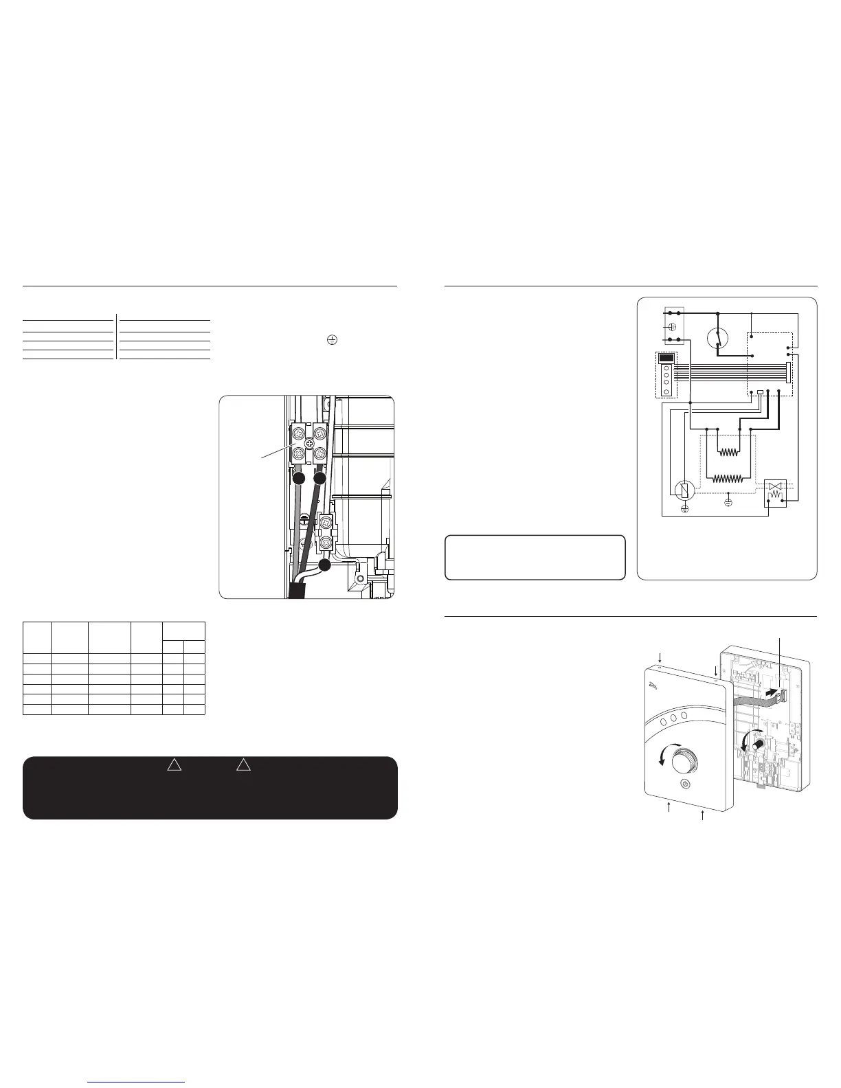
The diagram right shows a schematic wiring
diagram.
IMPORTANT: When connecting the cable fully
tighten the terminal block screws and make sure
that no cable insulation is trapped under the
screws. Loose connections can result in cable
overheating.
NOTE: The supply cable earth conductor must
be sleeved. The outer sheath of the supply cable
must be stripped back to the minimum.
The use of connections within the unit or
other points in the shower circuit to supply
power to other equipment i.e. extractor fans,
pumps etc. will invalidate the guarantee.
DO NOT switch on the electricity supply
until the shower cover has been fitted.
NOTE: The elements on UK models are to
240V specification and will give a lower kW
rating if the voltage supply is below 240V.
8. FITTING THE COVER BACK INTO POSITION
IMPORTANT NOTE: It is necessary to connect the
ribbon cable and align the temperature knob in the
cover with the opposite control spindle before the
cover is fitted.
First connect the ribbon cable to the 7 pin socket,
guides ensure it will only connect one way.
Then turn the Temperature knob anti-clockwise
to the stop.
Then in the internal unit make sure the Temperature
spline spindle is rotated fully anti-clockwise until it
reaches the stop.
The cover can now be fitted and secured with the four
fixing screws provided.
Re-fit the showerhead to the flexible hose.
Your shower is now ready to commission.
L
N
E
1
3
5
7
6
inlet
outlet
2
2
4
8
1 Terminal block
2 Element
3 Control PCB
4 Power PCB
5 Solenoid Valve
6 Thermal cut-out
7 Thermister
8 Connector socket
7. ELECTRICAL CONNECTIONS
ELECTRICAL SPECIFICATIONS
The shower unit must be permanently connected
to the electricity supply, direct from the consumer
unit via a double pole linked switch with a minimum
contact gap of 3mm. The switch must be readily
accessible and clearly identifiable and out of reach
of a person using a fixed bath or shower tray, unless
the switch is cord operated. The wiring must be
connected to the switch without the use of a plug or
socket outlet.
The cable size required is determined by the kW
rating of the shower and the distance between the
shower and the consumer unit. The table below
will help you choose the correct cable for your
installation, but it will depend upon the precise
circumstances of the installation. If you are in any
doubt consult an electrician.
The incoming cable should be hidden.
NOTE: the shower contains 2 separate sets of
connecting terminal blocks so the shower can be
wired for left or right installation with minimum effort.
Only connect to one of the terminal blocks.
The diagram below shows the route of the cable into
the shower unit for connection to the terminal blocks,
connect as follows:
Earth cable to terminal marked
Neutral cable to terminal marked N
Live cable to terminal marked L
IMPORTANT
Ensure that the terminal block screws are fully tightened and that no cable insulation is trapped under
screws. Ensure the cable clamp is used to secure the cable. The earth continuity conductor of the electrical
installation must be effectively connected to all exposed metal parts of other appliances and services in the
room in which the shower unit is installed to confirm


 To Next Page
 Loading...