2203M4JE-MY-iS2-N_2017.04.
Chapter 5 Maintenance
Screw Compressor i-series 5.5 Reassembly
5-23
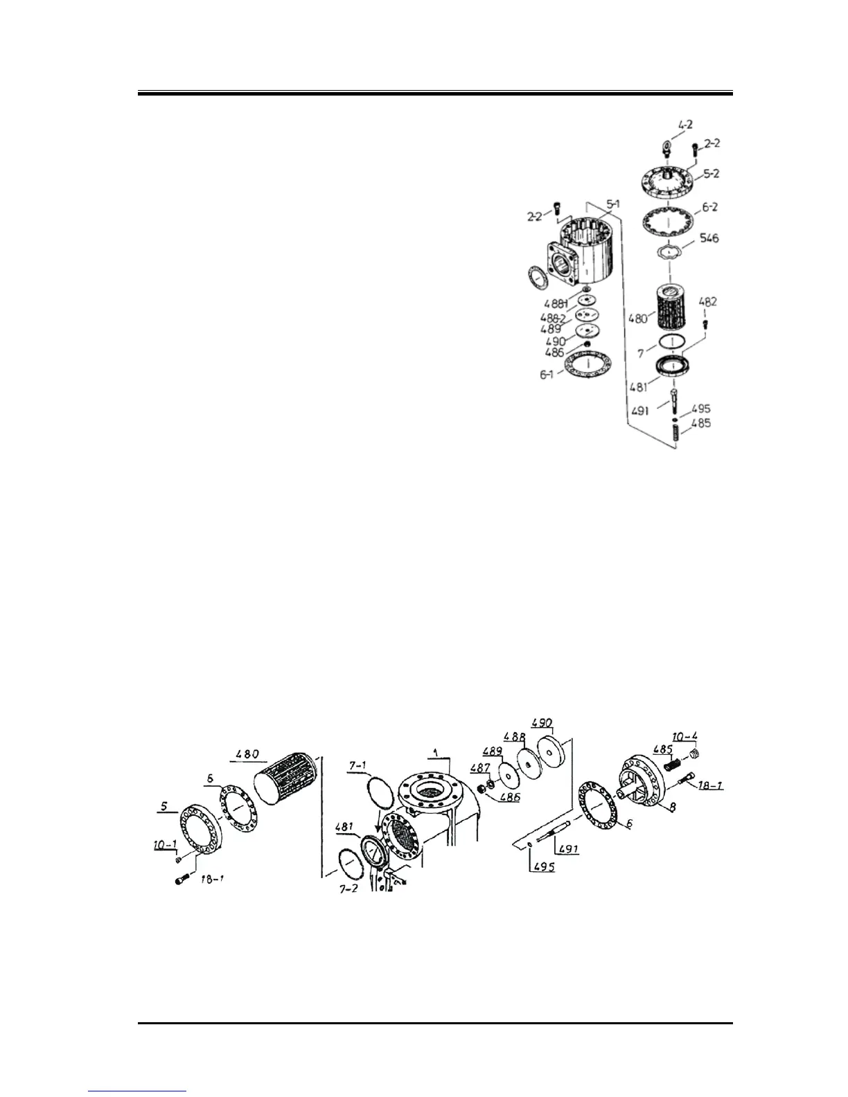
Figure 5-2 Suction Adapter part
(i125*)
5.5.5 Suction Strainer and Check Valve
The structure differs between the i125 series and i160 series.
5.5.5.1 i 125*
a) Set O-ring [495] and check valve spring [485] to check valve
shaft [491], and insert it to suction adapter [5-1].
b) While holding the check valve shaft with a hand to prevent it
from coming off, insert seat stoppers [488-1] [488-2], valve
seat [489], valve plate [490] and plain washer [46-2] in this
order. Tighten hexagon nut [486].
c) Install suction adapter gasket [6-1] and suction adapter to
main rotor casing. Check that the check valve functions
properly.
d) Assemble O-ring [7], strainer element [480] and wave
washer [546]. Install strainer cover gasket [6-2] and the
strainer cover [5-2].
5.5.5.2 i 160*
a) Install O-ring [495], valve plate [490], valve seat [489], seat
stopper [488] and plain washer [487] to check valve shaft
[491]. Tighten hexagon nut [486].
b) Insert the check valve shaft to the side of main rotor casing. Install strainer cover gasket [6] and
check valve cover [8].
c) Insert check valve spring [485], and attach a plug [10-4] to secure it.
d) From the strainer cover [5] side, confirm that the check valve operates properly.
e) Install O-rings [7-1] [7-2] to stainer element retainer [481].
f) Assemble stainer element retainer [481] and strainer element [480]. Install strainer cover gasket [6]
and strainer cover [5].
g) Install R1/8 plug [10-1] to the plug hole in the 6 o’clock position of the strainer cover.
Figure 5-3
Suction Strainer and Check Valve (i160*)