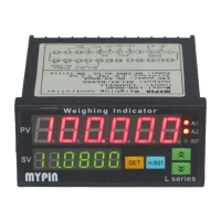
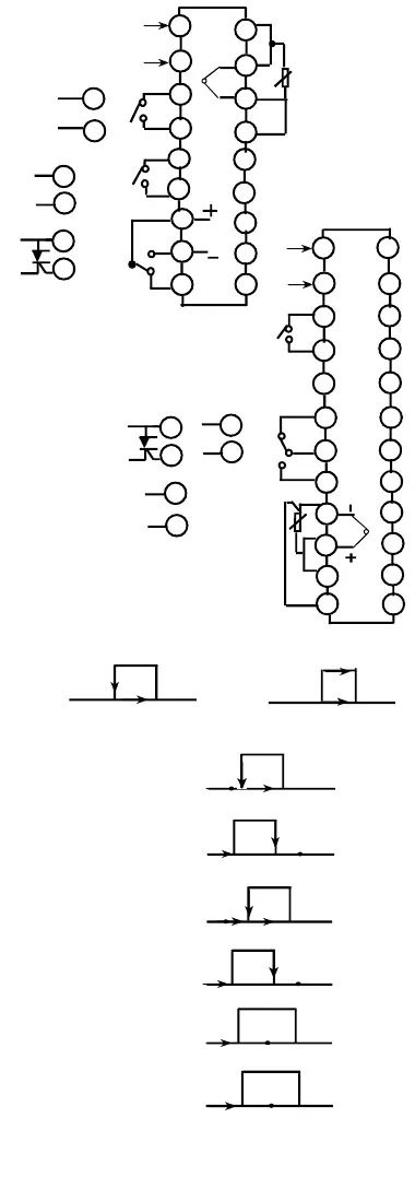
Terminal configurations
(If any changed, please refer to the product showing.)
③ Incorrect Control :
If the instrument has been used for a long
time, the user find the temperature is hard to rise up to the set
value, meanwhile the outsidesystem running well, there must be
something wrong with the parameters of the instrument.
The user need to re-autotuning the instrument. If the instrument
lost control, please check if the connection of the control is correct.
If external load is shorted, broken, wrong connection or compo-
nents is damaged, it will cause lost control as well.
④
Display malfunction : “UUUU”: The input signal exeed
the measured range, or check “USP” value.
ON/OFF control: ▲ Set value
←
LO HI
Alarm mode:▲ Set value △ Alarm value AL
LO HI
▲
↑
HYS
▲
Cooling
0:Deviation HI alarm
▲ △
↑
←
LO HI
1: Deviatian LO alarm
△ ▲
↑
←
LO HI
2: Absolute value HI alarm
▲ △
↑
←
LO HI
3: Absolute value LO alarm
△ ▲
↑
←
LO HI
4: Section outside alarm
△ ▲ △
HI
5: Section inside alarm
△ ▲ △
HI
Malfunction estimate
①
No Display : Check all the connection and wiring if it is all
correct. Specially pay attention to the power supply terminals and
signal input ternimals.
②
Incorrect Didplay: Check if the input signal is conformity with
the selected symbol.
For TC input, please use the relative compensation cable.
For RTD input, please use low impedence cable. The 3 wires
should at the same length.
If all above mentioned is collect , pleaase use parameter
PVF to modify.
Heating
ON OFF
Note:
All the factory setting value of deiation alarm is 1.0.
AL2 hysteresis setting value.
Range ± 90, factory setting 1.0
↓
Password setting.
Factory setting 015
Decimal point setting:
0: INT display 1: One decimal point
↓
↓
↓
↓
↓
↓
↓
HOLD SET
>3 S
↓
↓
↓
------------------------------------------
AL1 set range: –1999-9999
AL1 mode:
0: Deviation HI alarm 1: Deviation LO alarm
2: PV HI alarm 3: PV LO alarm
4: SV-PV > AL1 alarm 5: SV-PV <AL1 alarm
6: TC broken alarm, 7:The first Low won’t alarm
The factory setting is 2
AL2 mode: The same as AL1.
Offset value,range: ±100.
Display valuePV = Measured value - PVF
Input signal selection
stands for K, J, E, S,Pt100,Cu50 or mA/V/mV
The factory setting is K
Proportional band (%) range 0.1-3600.
If P=OFF, it means ON/OFF control
Integral time range 0.1-3600.
I=OFF means cancel integral time.
Derivative time range 0.1-3600. D=OFF means
cancel derivative time.
AL2 set range: –1999-9999.
↓
↓
↓
↓
↓
↓
Control hysteresis, range: ± 100.
It is not available when P ≠ OFF
Control Cycle Time(adjust to best fit your process)
Recommended starting settings: Relaly = 020sec
SSR =001sec. 4-20mA = 000 sec.
Control directions: HEAt: heating
COOL: cooling
Parameter lock code setting. LcK=000
means unlocked. LcK=010 means locked.
Temperature unit. C: ℃ degree,
F: F degree.
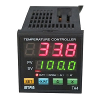
TA6/TA8/TA9
are subject to the drawing
on the product.
Only function for 4-20mA/0-10V
means PID control;
means 4-20mA/0-10V analog output
High analog output(when available)
eg. 10-100
℃
for 4-20mA output, trH=100
Low analog output (when available)
eg. 10-100
℃
for 4-20mA output, trL=10
5
4
3
2
1 0
9
8
6
7
1
1 2
1 1
+
-
TC/mV
←
+
-
+
-
SSR
1 2
1 1
SSR
4
3
←
+
-
TA7
90-260V AC/DC
7
4
3
2
1 3
1 2
1 0
1 1
1
A
B
B
+
-
5
6
9
8
1 8
1 7
NC
NO
OUT2/AL2
T1
G
▲
7
9
T2
4
3
+
-
+
-
8
7
1 5
1 4
1 6
T1
G
▲
8
6
T2
RTD
7
6
3
2
1 3
1 2
1 1
9
1 0
1
A
B
B
AL1
4
8
1 5
1 4
5
1 6
2 4
2 3
2 2
2 1
2 0
1 9
1 8
1 7
TC
COM
OUT1
6
8
+
-
4-20mA
Application examples
1.Relay output control (for TA7)
Power supply
Heating cord
Heating
equipment
5
4
8
7
6
2
1
16
15
14
12
11
10
17
J-1
FUSE
AL1
OUT1
C
R
J
←
90-260V AC
3
13
←
P t
NO
NC
9
18
RTD
▲
↑
↑
↓
OFF ON
HYS
HY
HY
OFF ON
HY
ON OFF
OFF ON
HY
ON OFF
ON OFF ON
OFF ON OFF
SSR
SSR
4-20mA
TC
AL1
RTD
Relay
Relay
OUT1
90-260V AC/DC
SSR
AL1
Relay
OUT1
4-20mA
RTD
TA4
AL2
A
B
B
90-260V AC/DC
COM
NC
NO
SET
SET
SET
SET
SET
SET
SET
SET
SET
SET
SET
SET
SET
SET
SET
SET
SET
SET
Note:
Please operate according to the process in this instruc
tion manual. Press <</AT key2s to enter auto-tune mode,
AT lamp ON, it goes off when auto-tuned.
In most cases you should start-out by placing your con
troller in auto-tune mode. Once auto-tuned, your con
trollers should not require additional auto-tune cycle if
the environment its working in changes little. If your
controllers is being used to heat or cool a load with a large
thermal mass, then the auto-tuned values need to be re
duced by 5% -10%.
The CtL setting.In most cases our control cycle should be
set to 10-20 seconds. For heating or coolin a load with a
large thermal mass, the value should be set to 30-40
seconds. If you are using a controller with a relay, setting
longer values will help to extend the life of your relay
contacts. Unless your process dictates longer cycle times,
the value should be set to 1-3 seconds to non-relay(SSR)
controls.The value should be set to 000 if 4-20mA cur
rent controls.
7
+
8
SSR
-
 Loading...