EasyManua.ls Logo

MYPIN TA Series - User Manual

MYPIN TA Series
8 pages
To Next Page IconTo Next Page
Loading...
TA Series of Temperature Controller
Instruction Manual
Thank you for selecting our controller!
Before operating this instrument, please carefully read this
manual and fully understand its contents. If any probroms,
please contact our sales or distributors whom you buy from.
This manual is subject to change without prior notice.
Warning
Please do not connect your controller to main power until
all of your wiring is complete and checked.Otherwise elec-
trical shock, fire or malfunction may result.
Do not wire when the power is on. Do not turn on the
power supply when cleaning this instrument. Do not
disassemble, repair or modify the instrument. This may
cause electrical shock, fire or malfunction.Use this instru-
ment in the scope of its specifications. Otherwise fire or
malfunction may result. The internal relay’s service life is
greatly dependent on the current and voltage switched by
its contacts. Over-stressing the contacts with too much
current or switching vltage above the contact rating will
greatly shorten the life of the relay.
Applications
TA series of temperature controller is available for many TC
or RTD input, adopt some advanced techonology such multi
digital filter circuit, autotune PID, fuzzy PID that make it
is very precise, stable, strong anti-interference and
simple operation. The instrument is widely applied to
Panel
This instrument is not rated foroutdoor use and should be used in
a climate controlled environment.
Installing in an environment heavy laden with dust or contain-
ing corrosive gasses will cause your controller to fail.
Do not install near water spray, oil spray, or in an environ-
ment where water can condense inside the unit.
Avoid running power leads in parallel with high voltage or
heavy current carrying conductors that may induce high
voltages into the unit. If you must run incoming power
near high voltage or heavy current carrying conductors, we
suggest that you run the power inside metal conduit that is
grounded on one end only.
If installing in an electrically noisy environment, we sug-
gest that you protect the unit with a current suppressor or
noise filter.
Power supply 90-260V AC/DC 50/60Hz
Consumption 5VA
Display range -1991800
Accuracy 0.3%F.S ± 2digit
Sampling cycle
300ms
Main output RELAY:normal open AC 250V/5A DC 30V/5A COS=1
SSR/LOGIC:24V DC ± 2V/ 20mA
Specifications
RELAY: normal open AC 250V/5A DC 30V/5A COS=1
SSR/LOGIC:24V DC ± 2V/ 30mA
K 0~1200(negtive temp customized)
J 0~1200(negtive temp customized)
T -150~400 (customized only)
S 0~1600
Rt Pt100 -199~600
Cu50 -50~150
Alarm
Input
T/C
Withstand voltage strength
Others
Please mention when ordering
1500V Rms
(Between power terminal and the housing)
Min 50M
Ω(
500VDC
)
(Between power terminal and the housing)
Environment temperature
Storage temperature
Environment humidity
Weight
0~50
-10~60
35~85%RH
Insulation resistance
Mounting and Sizes
D
B
A
E
C
G
H
Sizes
Model
TA4
TA6
TA9
TA7
44.5+0.5 45+0.5 65 65 48 48 8 80
43.5+0.5 91+0.5 65 115 48 96 12 80
91+0.5 91+0.5 95 95 96 96 12 80
67.5+0.5 67.5+0.5 115 115 72 72 12 80
A B C D E F G H
Parameter Setting
Setting steps
A: Select the parameter you want to modify
B: Press the
/AT key to select the digit you
want to modify
C: Press key and key to modify the numerals
D: Press SET key to confirm
Power on
Displays temperature unit
Input UP limit
3S
3S
3S
Measured displaying(PV)
Set displaying(SV)
Shift and flashes
Modify SV preset value
SET
Stop flashing
Confirm
Self-check
All LED on
Input type
350g
E 0~1000
Caution
TA8
91+0.5 43.5+0.5 65 115 96 48 12 80
Input LOW limit
In Non-autotune estate, press and hold / key for more
than 5 seconds can enter/quit the under menu: (Normally
the program will refresh the value of the parameters
by itself, the user no need make modifications. )
1
Low display value, it is adjust-
able by the input signal.
eg. K type 0-800C, LSP=0.0
automation systems of mechanism, chemical industrial,
chinaware, light industrial, metallurgy and petroleum chemical
industrial. It is also applied to the production line of foodstuff,
packing, printing, dry machine, metal heat process equipment
to control the temperature.
Up display value, it is adjustable
by the input signal.
eg. K type 0-800C, USP=100.0
AL1 hysteresis setting value.
Range ± 90, factory setting 1.0
SET
O U T 1 O U T 2
ATAL
SET
TA
>
>
>>
/AT
PV
SV
. PV / parameter symbols
. SV / parameters set value
. Indication lamps
OUT1: Heating/Main control output lamp
On: Output Off: No output
OUT2:
Alam2 output lamp
On: Output Off: No output
AT: On: Autotune Off: Non-autotune
AL: Alarm 1 lamp On: Alarm Off: No Alarm
.Set key Parameter Setting/Changing
.Shift/Autotune key
Press this key to shift digit of parameter value setting.
Or hold this key for more than 3s can enter/quit autotune
estate. When enter autotune estate, AT lamp on. When
quit autotune estate, AT lamp off.
.Up key .Down key
TA
□□ - □□□□
Models
Input signals:Default: K,J,E, S,PT100,Cu50
1:4-20mA/0-10V/0-75mV F: others
OUT2/AL2:R: RELAY S: SSR/Logic
T: SCR N: None
OUT1: I: 4-20mA V:0-10V DC
R: RELAY S: SSR/Logic
AL1:R:RELAY S:SSR/Logic T:SCR
Power supply: Default:90-260V AC/DC
E: 24VDC or 18-30V AC/DC
Sizes 4: 48H × 48W 6: 48H × 96W
TA series of temperature controller
7: 72H × 72W 8: 96H × 48W 9: 96H × 96W
/AT
F
MYPIN
SET
SET
TEMPERATURE CONTROLLER
>
>
Question and Answer IconNeed help?

Do you have a question about the MYPIN TA Series and is the answer not in the manual?

MYPIN TA Series Specifications

General IconGeneral
Input SignalThermocouple, RTD
OutputRelay
DisplayLED
Accuracy0.2%FS
Operating Temperature0°C to 50°C (32°F to 122°F)
MountingPanel Mount

Summary

Panel Overview and Controls

PV and SV Parameter Symbols

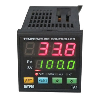
Identifies PV/parameter symbols and SV/parameter set values on the controller display.

Indication Lamps Explained

Details the function of OUT1, OUT2, AT, and AL indicator lamps.

Keypad Functions

Explains the operation of Set, Shift/Autotune, Up, and Down keys for parameter interaction.

TA Series Models and Specifications

Model Input and Output Configurations

Details input signal types, output configurations (RELAY, SSR/Logic, SCR), and alarm options.

Power Supply and Physical Sizes

Lists available power supply voltages and the physical dimensions of TA series models.

Technical Specification Summary

Provides key specifications including power, consumption, display range, accuracy, and sampling cycle.

Input Signal Types and Ranges

Details supported input signals such as T/C (K, J, T, S, E) and Rt (Pt100, Cu50).

Electrical Ratings and Environmental Conditions

Covers withstand voltage, insulation resistance, operating/storage temperatures, and humidity.

Mounting and Dimensions

Mounting Hole Diagram

Illustrates the standard mounting hole layout for the controller.

Model Dimension Details

Table detailing dimensions (A, B, C, D, E, F, G, H) for various TA models.

Parameter Setting and Configuration

Basic Parameter Adjustment Steps

Guides through selecting, modifying digits, and confirming parameter values.

Autotune Mode Entry and Exit

Procedure to enter and exit the autotune state via the << / AT key.

Display Value Calibration (LSP;USP)

Adjusting the low (LSP) and high (USP) display values based on input signal.

Alarm 1 Hysteresis Setting

Configuring the hysteresis value for the first alarm (AL1).

Alarm 2 Hysteresis and Decimal Point

Setting AL2 hysteresis, decimal point display, and password.

Alarm Mode Configuration

Detailed explanation of available AL1 and AL2 alarm modes (Deviation, Absolute, etc.).

PID Control Parameter Tuning

Setting offset, proportional band (P), integral time (I), and derivative time (D).

Control Direction and Cycle Time

Setting heating/cooling direction, hysteresis, and control cycle time (CtL).

Analog Output and Unit Settings

Configuring low/high analog output scaling and temperature units (°C/°F).

Parameter Lock Code Setting

Procedure for setting a parameter lock code to prevent unauthorized changes.

Terminal Configurations and Wiring

TA4 Terminal Connections

Diagram showing terminal numbering and connections for the TA4 model.

Operating in Autotune Mode

Instructions on how to initiate and operate the controller in autotune mode.

Control Cycle Time (CtL) Guidelines

Recommendations for setting CtL based on load type and output relay life.

TA7 Terminal Connections

Diagram showing terminal numbering and connections for the TA7 model.

TA6;TA8;TA9 Terminal Connections

Diagram showing terminal numbering and connections for TA6, TA8, and TA9 models.

ON;OFF Control and Alarm Modes

Explanation of ON/OFF control behavior and various alarm mode configurations.

Application Examples and Troubleshooting

Relay Output Control Example (TA7)

Wiring example for relay output control on a TA7 model.

Troubleshooting: No Display

Steps to diagnose and resolve 'No Display' issues, checking wiring and power.

Troubleshooting: Incorrect Display

Diagnosing display errors related to input signal conformity and cable types.

Troubleshooting: Incorrect Control

Resolving issues where the instrument fails to reach set values or maintain control.

Troubleshooting: UUUU Display Malfunction

Understanding the 'UUUU' error, indicating input signal range or USP value issues.

Related product manuals