TD Series Temperature Controller
Instruction Manual
Thanks a lot for selecting the product!
Before operating this instrument, please carefully read this
manual and fully understand its contents. If any probroms,
please contact our sales or distributors whom you buy from.
This manual is subject to change without prior notice.
Warning
Please do not turn on the power supply until all of the wiring is
completed. Otherwise electrical shock, fire or malfunction
may result.
Do not wire when the power is on. Do not turn on the
power supply when cleaning this instrument. Do not
disassemble, repair or modify the instrument. This may
cause electrical shock, fire or malfunction.Use this instru-
ment in the scope of its specifications. Otherwise fire or
malfunction may result.The use life of the output relay is
quite different according to is capacity and condictions. If
use out of its scope, fire or malfunction may result.
Applications
TA series of temperature controller is available for many TC
or RTD input, adopt some advanced techonology such multi
digital filter circuit, autotune PID, fuzzy PID that make it
is very precise, stable, strong anti-interference and
simple operation. The instrument is widely applied to
Panel
This instrument should be installed in a domestic environment.
Otherwires electricla shock, fire or malfunction may result.
To avoid using this instrument in environment full of dust
or caustic gas.
To avoid using this instrument in environment of strong
shock or concussion.
To avoid using this instrument in environment of overflow
water or explosive oil.
The power supply wire should not put together with large
current wire to aviod electromagnetic radiation, If it must to
put together, we suggest to use a individual pipe.
In case the instrument is used in environment of strong noise,
(such as motor, transformer, solenoid, etc.) A current suppresser
or noise filter should be used.
Power supply 90-260V AC/DC 50/60Hz
Consumption ≤ 5VA
Display range -199~1800℃
Accuracy 0.3%F.S ± 2digit
Sampling cycle
≤ 300ms
Main output RELAY:
normal open
AC 250V/3A DC 30V/3A COS¢=1
SSR/LOGIC :24V DC ± 2V/ 20mA
Specifications
RELAY:
normal open
AC 250V/3A DC 30V/3A COS¢=1
SSR/LOGIC:24V DC12V/ 30mA
K 0~999℃/0~1200℃
J 0~999℃ /0~1200℃
T -150~400℃ (Special order)
S 0~1600℃
Rt Pt100 -199~600℃
Cu50 -50~150℃
Alarm
Input
T/C
Withstand voltage strength
1500V Rms
(Between power terminal and the housing)
Min 50M Ω(500V DC)
(Between power terminal and the housing)
Environment temperature
Save temperature
Environment humidity
Weight
0~50℃
-10~60℃
35~85%RH
Insulation resistance
Mounting and Sizes
+
+
+
↑
D
↑
B
A
↑
↑
E
↑
↑
C
↑
G
H
Sizes
Model
TD4
TD6
TD9
TD7
44.5+0.5 45+0.5 65 65 48 48 8 80
43.5+0.5 91+0.5 65 115 48 96 12 80
67.5+0.5 67.5+0.5 95 95 72 72 12 100
91+0.5 91+0.5 115 115 96 96 12 100
A B C D E F G H
Parameter Setting &Autotuning
☆ Parameters setting:
A: In display estate,press SET,P/MV lamp on means SV setting,
while off means MV manual output setting,but only on manual
operation & input connect do MV settable. B: Press the
<<
/
M
key to select the digit you want to modify; C: Press and
key to modify the numerals; D: Press SET key to confirm.
☆ In autotuning estate,output value modification is
impossible.
☆ Antotuning operation.
In display estate,press SET and <</M key at the same time
until AT/M lamp flahses.Then ithe instrument is under
autotuning estate.Press again to quite.
Power on
↓
↓
Displays temperature unit
↓
Input up limit
3S
3S
3S
Measured displaying
Set displaying
↓
Shift and flashes
Modify
SET
Stop flashing
↓
Confirm
Self-check
All LED on
Input type
≤ 350g
E 0~1000℃
Caution
TD8
91+0.5 43.5+0.5 65 115 96 48 12 80
Input low limit
↓
In Manual operation/Non-autotune estate, press and hold
/ key for more than 3 seconds to enter/quit the below
menu for display range settings.
SET
↓
>>
>
>
Low limit value, it is adjustable
by the input signal.
automation systems of mechanism, chemical industrial,
chinaware, light industrial, metallurgy and petroleum chemical
industrial. It is also applied to the production line of foodstuff,
packing, printing, dry machine, metal heat process equipment
to control the temperature.
Up limit value, it is adjustable
by the input signal.
↓
SET
AL1 hysteresis setting value.
Range ± 90, factory setting 1.0
SET
↓
TD
□□ - □□□□
Models
Input signals:Default: K,J,T,S,Pt100/mA,lN
OUT2/AL2: R:RELAY S:SSR/Logic
-T:SCR N:Non
OUT1: I:4-20mA R:RELAY
S:SSR/Logic T:SCR
AL1:R:RELAY S:SSR/Logic T:SCR
Power supply:Default:90-260V AC/DC
E:24VDC or 18-30V AC/DC
Sizes: 4:48H × 48W 6:48H × 96W
TA series of temperature controller
7:72H × 72W 8:96H × 48W
9:96H × 96W
>>
>
>
/M
F
+
↑
↑
↑
MYPIN
mV
mV 0-75mV
mA mA
4-20mA /0-10V
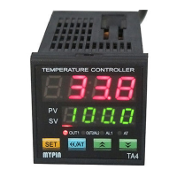
①. PV / parameter symbols
②. SV / parameters preset value
③. Indication lamps
OUT1: Heating/Main control output lamp
On: Output Off: No output
OUT2/AL2:
Colling/Alarm 2 output lamp
On: Output Off: No output
AT/M: On: manual operation Off: auto operation
Flash: under autotuning estate
P/MV: SV/MV display setting
On: MV manual output Off: SV setting
AL1: Alarm 1 lamp On: Alarm Off: No Alarm
AL2: Alarm 21 lamp On: Alarm Off: No Alarm
④.Set key Parameter Setting/Changing
⑤.Shift/Autotune key Press this key to shift digit of
parameter value setting. Or hold this key for more than 3
seconds can enter/quit autotune estate. When enter
autotune estate, AT lamp on. When quit autotune estate,
AT lamp off.
⑥.Up key ⑦.Down key
↑
O U T 1
O U T 2 /
AT/M
AL1
SET
>
>
/M
PV
SV
①
②
③
④
→
→
→
↑
↑
⑥⑤
→
P / M V
A L 2
>
>
>
>
⑦
>>
>
>