AC ELWA
®
Installation and Operating, Version 1.0, Date 2016-01-23 5
Control line between AC ELWA and PLA
The control cable between AC ELWA and PLA may be installed in AC wiring conduits. There is no separate
installation necessary (local regulations must be observed!)
The strain relief of the connector must be mounted. Exposed areas of the control line need double
insulation! The entry of the control line in the wall socket must comply with local regulations (strain relief).
The control cable for PLA is attached to the two-pin plug to the AC ELWA. (0,5 - 1,5 mm²). The poles (L and
N) on the connector are short-circuited inside the unit, so that a redirect to other AC ELWAs (up to 6) is
possible.
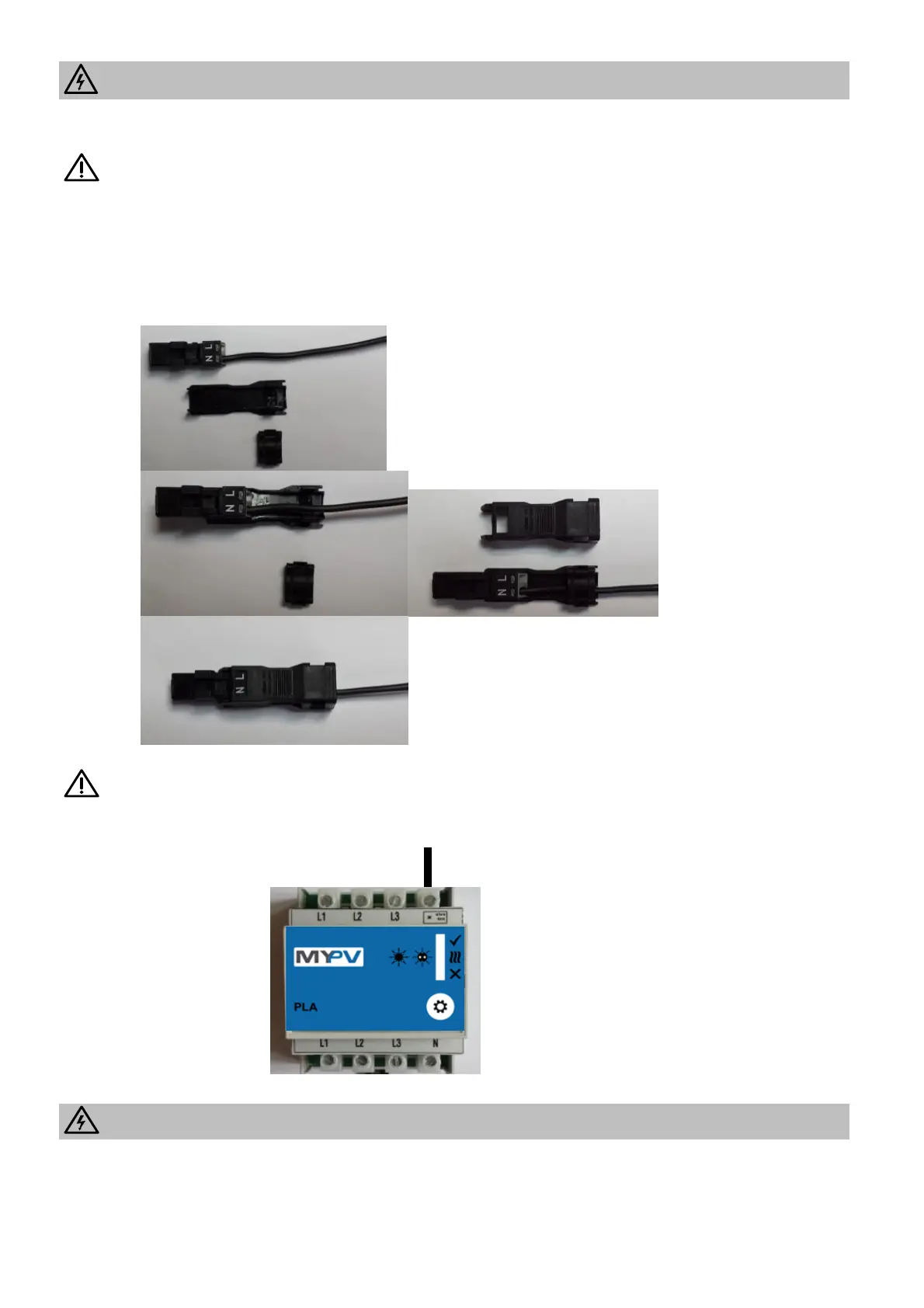
Installation of the plug:
The labels L and N on the connector have no meanings! Never connect the control wire with L or N of
the wall socket!
Connection of the control line at the PLA:
Electrical connection of several AC ELWAs in a system
All AC ELWAs (max. 6) should be connected to appropriate AC circuits.
Warning: any AC ELWA can take up to 3 kW!
It is recommended to divide the ELWAs on the 3 phases.
Note: More than 6 ELWAs can be controlled with the Universal Interface via RS485.
 Loading...