03
KICKSPACE
®
500, 600, 600-12V, 800, 80S & 80D
2.0 Installation
l Before proceeding with the installation, the heating system
design must be considered and the unit correctly sized to
meet the heat loss requirements of the room.
l Before proceeding with the installation, unpack the carton
contents and check against the checklist below:
1. KICKSPACE
®
unit.
2. Flexible hoses including isolating valves (1 pair).
3. Instruction manual.
4. Grille - supplied seperate.
5. Screw fixing kit (with grille) - supplied seperate.
6. Transformer (12V model only).
7. Connector (12V model only).
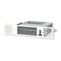
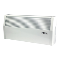
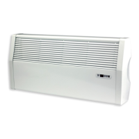
l This MYSON KICKSPACE
®
fan convector is designed for
installation in the cavity beneath kitchen cupboards on the
vacant floor space, or other similar locations.
l For KICKSPACE
®
500, 600, 600-12V & 800 a minimum of
25mm clear headroom is required above the top of the
KICKSPACE
®
when fitted.
l The unit should be mounted on a clean and level floor area
under the cupboard base.
l KICKSPACE
®
80S & 80D models can only be installed if there
is a minimum height of 80mm from the top of the floor
covering to the underside of the kitchen unit (see Fig. 1).
l KICKSPACE
®
500, 600, 600-12V & 500 floor mounting (see
Fig. 2a) - The KICKSPACE
®
is normally fitted directly onto the
floor and the base of the unit is fitted with four mounting feet.
l KICKSPACE
®
500, 600, 600-12V & 500 plinth mounting
(see Fig. 2b) -
• As an alternative to floor mounting the unit may be fitted
into the plinth.
• A suitable support must be securely fitted to the floor.
• The top of the support must be level with the lower edge of
the cut-out when fitted.
l KICKSPACE
®
80S & 80D floor mountings (see Fig. 2c) - Applies
to 80S & 80D units in 80mm plinth height kitchen unit.
l Decide the position of the KICKSPACE
®
, mark out and cut the
plinth to the dimensions using table on page 9.
l Position the KICKSPACE
®
under the cupboard in the required
location, with the front edge just behind the line of the plinth.
l Replace the plinth and bring the KICKSPACE
®
forward into
the opening so the front edge projects approximately 10mm
through the plinth.
l Align the grille and secure it to the unit with two screws
supplied (use the shorter screws). (See Fig. 3).
l Secure the unit/grille to the plinth with two screws supplied
(use the longer screws). (See Fig. 3).
l Complete the electrical installation, switch on and test the
KICKSPACE
®
(see Fig. 3).
l When installed in a kitchen consideration should be given to
storage of perishable goods in the cupboard above.
3.0 Water Connection
l The KICKSPACE
®
should only be used on closed circulation,
two pipe, pump assisted central heating systems.
l For optimum fan convector heating performance the system
must be capable of providing sufficient hot water through the
heat exchanger. This means that:
1. The minimum pipe size from boiler to fan convector must
be at least 15mm. Microbore pipe MUST NOT be used.
2. Where the unit is fitted on to a system with other emitters
a separate circuit for the fan convector should be
considered to provide adequate water flow.
3. The system water temperature on the return of the
KICKSPACE
®
must be above 30°C for the fan to switch on.
4. This unit is NOT suitable for one-pipe systems.
5. Optimum performance will require effective balancing of
the whole system.
6. This unit must not be used to replace a radiator in an
existing system unless an adequate flow of water can be
guaranteed.
l Connect valve ends of the flexible pipes to the KICKSPACE
®
.
Note: The direction of the arrows on the valves are not
significant in this application (see Fig. 4).
l Open valves fully, check pipe connections for leaks and vent
the heat exchanger. A vent screw is provided to vent the heat
exchanger.
Pipework must be positioned correctly to ensure
flexible hoses are not kinked when installed
(see Figs. 5a & 5b). Only use the hose sets
supplied with this unit. Do not use old or
alternative hose sets.
KICKSPACE
®
500, 600, 600-12V, 800, 80S & 80D
INSTALLATION & OPERATING MANUAL
01.07.2018
EN