3.5 Tool constant settings
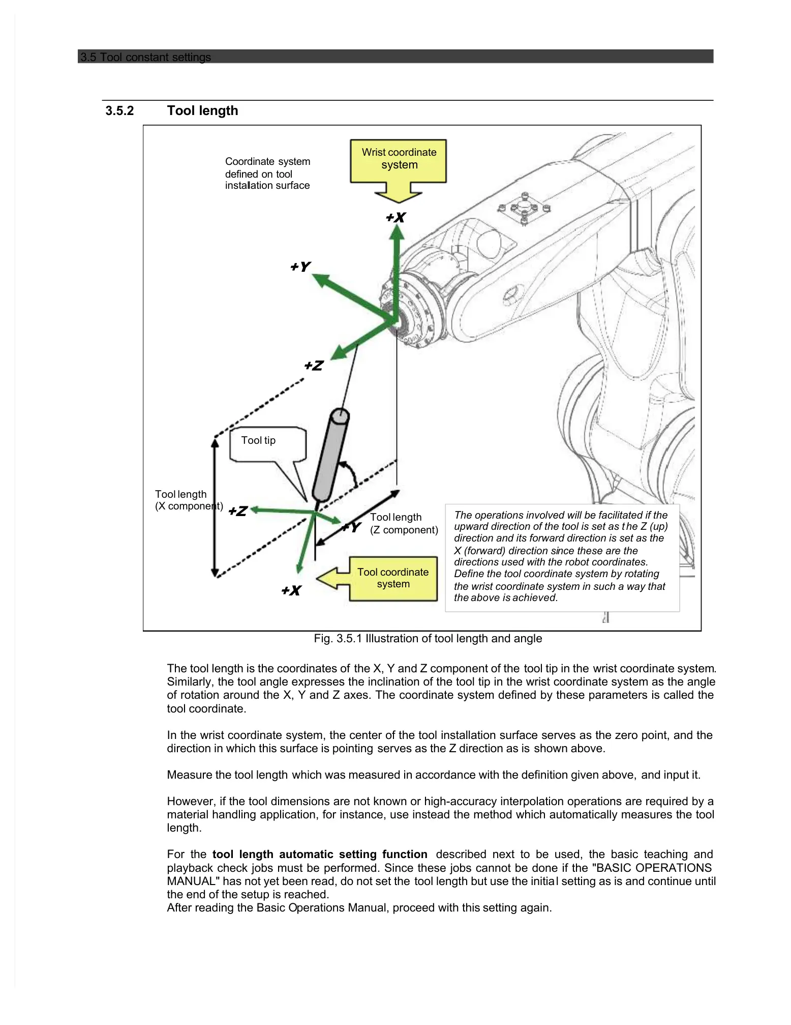
The operations involved will be facilitated if the
upward direction of the tool is set as t
direction and its forward direction is set as the
X (forward) direction si
directions used with the robot coordinates.
Define the tool coordinate system by rotating
the wrist coordinate system in such a way that
Fig. 3.5.1 Illustration of tool length and angle
The tool length is the coordinates of
the X, Y and Z component of the
Similarly, the tool angle expresses the inclination of the tool tip in the wrist coordinate system as the angle
of rotation around the X, Y and Z axes. The coordinate system defined by these parameters is called the
In the wrist coordinate system, the center of the tool installation surface serves as the zero point, and the
direction in which this surface is pointing
serves as the Z direction as is
which was measured in accordance with the definition given above,
However, if the tool dimensions are not known or high-accuracy interpolation operations are required by a
material handling application, for instance, use instead the method which automatically measures the tool
tool length automatic setting function
described next to be used, the basic teaching and
playback check jobs must be performed. Since these jobs cannot be done if the "BASIC OPERATIONS
MANUAL" has not yet been read, do not set the
tool length but use the initia
l setting as is and continue until
the end of the setup is reached.
After reading the Basic O
perations Manual, proceed with this
 Loading...