Do you have a question about the Naigai NAG-144XL and is the answer not in the manual?
Caution against high voltage present in the unit during operation.
Procedure for safely replacing the output tube, including discharging.
Innovative front panel tuning for optimal performance and reduced spurious radiation.
Details on different models based on output and tubes used.
Forced-air cooling, warm-up timer, thermal protector, and optional timer delay.
Coaxial relays, ALC circuit, external control, and DC-DC converter option.
Measures transmitting output and standing wave ratio.
Controls for plate tuning and antenna coupling adjustment.
Switches for power, amplifier operation modes, and receiver booster.
Controls for delay adjustment and bias voltage.
Connectors for power supply, antenna, ground, and exciter input.
Socket for interlocking operation with exciter and control signals.
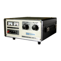
Detailed description of meters and tuning controls on the front panel.
Explanation of the power switch and OPER/ST BY/DELAY modes.
Controls for the receiver amplifier and SWR meter adjustments.
Detailed description of bias, delay controls, and power supply.
Explanation of each pin and its function within the control socket.
Details on RF input, RF output, and ground terminals.
Operation of the power switch and the function of the warm-up timer.
How to use the OPER, ST BY, and OPER DELAY switch positions.
Switching the receiver amplifier on and off.
Using the meter for RF output and SWR measurements.
How to adjust PA TUNE and PA LOAD for maximum output.
Important considerations for placing the unit to ensure proper cooling.
Connecting the exciter and antenna using coaxial cables.
How to connect AC power and the location of the AC fuse.
Interlocking operations, ALC input, and grounding terminal.
Adjusting bias voltage and timer delay for optimal performance.
Details on the 13.5V DC regulated power supply output.
Wiring diagrams for connecting with popular transceivers like TS-700, FT-221.
Ensuring proper ALC feedback and ground connections for clean radio waves.
Automatic transmission/reception via carrier control without external relay.
Using the 13.5V DC supply and details on cabinet legs for stability.
Ensuring correct connections and setting initial controls before operation.
Step-by-step procedure to adjust PA TUNE and PA LOAD for peak output.
Tips for optimal tuning and warnings about continuous transmission.
How to adjust the SWR meter for antenna matching and performance.
Turning the RX AMP on/off and cautions regarding its adjustment.
Advice for users regarding cooling transmitting tubes after operation.
Procedure for replacing tubes and adjusting frequency indicators.
Optional timer delay unit for blower to cool tubes after power off.
How to mount the DC-DC converter for 12V battery operation.
