Nailor Industries Inc. reserves the right to change any information concerning product or specification without notice or obligation.
6/20 IOM-EHVAV (Supercedes 4/02)
Page 2 of 4
FAN POWERED
(UNITE TERMINALE @
TERMINAL UNIT
VENTILATEUR INTEGRÉ)
DATE (DATE) : 27-Nov-2001 SERIAL NO. (NO. DE SÉRIE) : 150111-2
MODEL (MODÈLE) : D35SE TAG NO. (NO. DÈTIQUETTE) : FPB-1-35
UNIT SIZE-INLET SIZE : 4-10 VOLTAGE (VOLTAGE) : 480
(DIAMETRE D’ENTRÉE) PHASE (PHASE) : 3
CONTROL VOLTAGE : 24 STAGES (ÉTAPES) : 2
(VOLTAGE DE CONTRÔLE) HZ. (HZ) : 50/60
CONTROL SEQUENCE : NB MOTOR HP (MOTEUR HP) : 1/3
(SEQUENCE DE CONTRÔLE) MOTOR VOLTAGE : 277
VOLT AMP (VOLT-AMPÈRE) : 50 (VOLTAGE DU MOTEUR)
HOT WATER COIL ROWS : N/A MOTOR AMP : 2.0
(NOMBRE DE RANGÉES SERPENTIN EAUCAUDE) (AMPERAGE DU MOTEUR)
KW/HP AMPS AMPACITY MAX. OVERCURRENT PROTECTION MOTOR FUSE SIZE
(AMPÈRES) (AMPACITÉE) (RESISTANCE DES FUSIBLE MAX.) (MOTEUR FUSIBLE)
TOTAL EACH CIR. EACH STG. TOTAL EACH CIR. EACH STG. TOTAL EACH CIR. EACH STG. TOTAL EACH CIR.
(TOTALE) (CHAQUE (CHAQUE (TOTALE) (CHAQUE (CHAQUE (TOTALE) (CHAQUE (CHAQUE (TOTALE) (CHAQUE
CIRCUIT) ÉTAPE) CIRCUIT) ÉTAPE) CIRCUIT) ÉTAPE) CIRCUIT)
HEATER (CHAUFFAGE)
10.0 10.0 5.0 12.0 12.0 6.0 15.0 15.0 7.5 20 20 N/A
MOTOR (MOTEUR)
1/3 2.0 2.5 3 30
TOTAL (TOTALE)
14.0 17.5 23
EACH ELEMENT RATED @ 3.3 KW @ 277 VAC. AWG. MIN WIRE SIZE (MIN DIAMETRE DE FIL) : 14
(CHAQUE ELEMENT CLASSIFIER A) MIN. HEATING CFM (MIN. PCM) : 700
USE WIRE SUITABLE FOR AT LEAST 75 oC UTILISER UN FIL METALIQUE QUI CONVIENT AU MOIN 75 oC
L1 IS COLOR CODED BLACK , L2 IS BLUE, L3 IS RED L1 EST COLORÉ NOIRE, L2 EST BLUE , L3 EST ROUGE,
CONTROL WIRES CODED AS MARKED LES FILS DE CONTRÔLE SON INDENTIFIÉE COMME MARQUE,
USE COPPER CONDUCTORS ONLY. UTILISÉ DES CONDUCTEURS DE CUIVRE SEULEMENT.
USE CLASS K, RK1, A2D OR A6D FUSE OR HACR BREAKERS. UTILISÉ DES FUSIBLES CLASS K, RK1, A2D, OU A6D OU HACR DISJONCTEURS.
PRIMARY CFM (MAX/MIN) : 1000/1000 PRIMARY L/S (MAX/MIN) : 472/472
FAN CFM : FAN L/S :
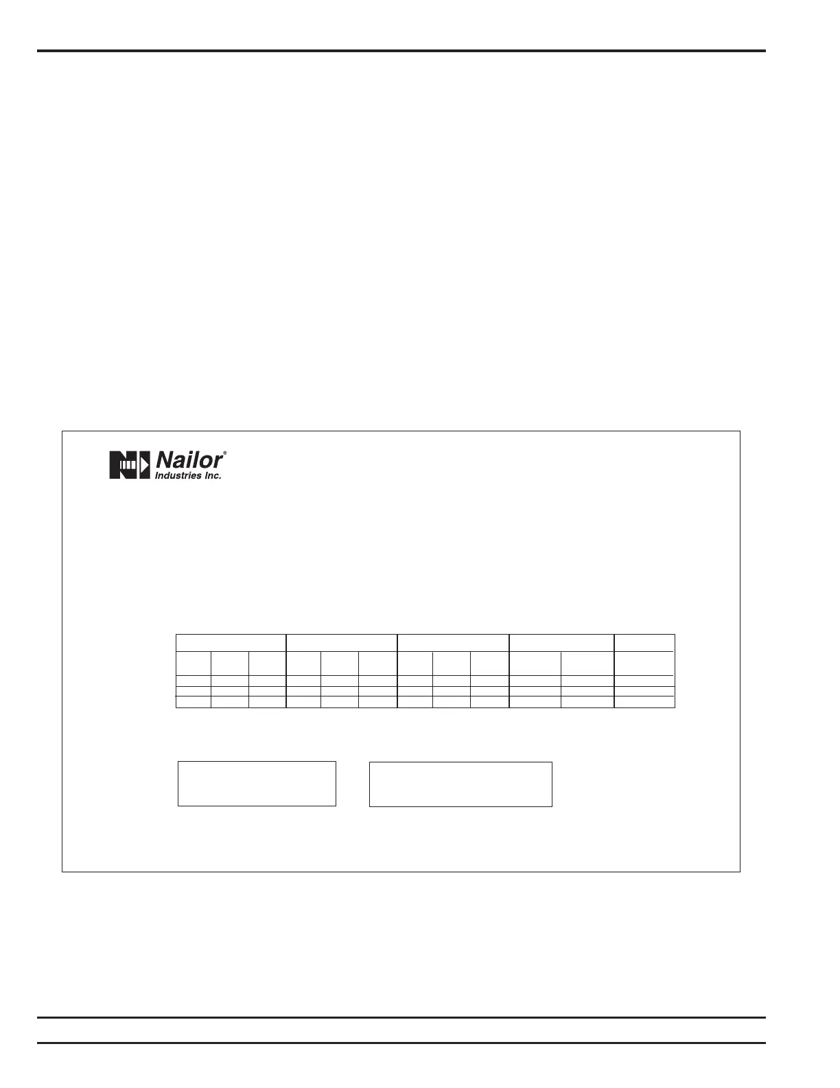
NAMEPLATE LABEL
Electric coil data are incorporated in the nameplate label,
which is affixed to the control enclosure cover. The label
shows all necessary information required by UL with respect
to electrical power and circuit protection requirements.
HEATER CONTROL ENCLOSURE
Figure 4 shows the interior of a typical heater control
enclosure. All components within this space work together
to provide safe operation of the heater. Although it is not
required to meet NEC requirements, Nailor recommends a
door interlocking disconnect switch. This safety switch
must be disconnected before the enclosure can be opened.
In the absence of a disconnect switch, a terminal block
is provided for single point power connection. A ground
lug ensures the proper grounding of the unit housing and
enclosure. Line fuses and fan motor fuses provide
overcurrent protection, and come as an option. An airflow
switch de-energizes the heater when it detects no airflow
across the elements.
In fan powered VAV terminal units, auto-reset limit
switches in line with each element provide high temperature
protection. A single auto-reset limit switch provides
protection for single duct terminal unit heaters. These
switches automatically cut the heater off when overheating
occurs, and turn the heater back on when the elements have
cooled down. Manual-reset limit switches in line with each
element provide secondary over temperature protection in
single duct terminal units.
A control transformer is provided whenever a 24V circuit
is required. PE switches (when pneumatic controls are
used), like magnetic contactors, are used to energize
stages of electric heat. Small heaters may often use a load
carrying PE switch as the only control component. When
control systems require frequent cycling or silent operation,
mercury contactors are available as an option. An SCR
control will provide fine space temperature control and
highest reliability. For fan-powered terminal units, a fan
relay is provided when required or requested.
Figure 3. Sample Nameplate Label. Fan Powered Terminal Unit
 Loading...