Nailor Industries Inc. reserves the right to change any information concerning product or specification without notice or obligation.
INSTALLATION AND OPERATION MANUAL
ELECTRIC HEATERS FOR
VAV TERMINAL UNITS
Page 1 of 4
6/20 IOM-EHVAV (Supercedes 4/02)
GENERAL INFORMATION
• Nailor electric heaters require little or no maintenance.
Be sure the heater elements are free of foreign matter,
and then check that the connections are tight and proper
control interlocks have been made before turning the
heater on.
• Heaters are open wire type and, except on very small
heaters with element wires less than 1 kW, use special
‘arrowhead’ insulators that expose the entire surface area
of the element wires to the air stream. This eliminates the
possibility of hot spots on the larger wires that can burn
the elements in half or cause spalding that enhances hot
spots.
• All electric heaters ordered from Nailor are manufactured
in-house.
• All Nailor electric coils are ETL listed for safety under UL
1995 as part of the VAV unit.
• All electric heating units have built-in controls for all
options required by the engineer.
• Single point power connection.
INSTALLATION
• All single duct terminal units with electric coils are
designed to be mounted in a horizontal plane with respect
to the "UP" arrow marked on the product label. Fan
powered units can be flipped over in the field and will not
have "UP" arrow.
• Before applying power, make sure electric coils are not
damaged.
• All field wiring must comply with NEC and local building
codes.
• Use copper conductors only.
• Phase rotation of the incoming power is recommended
when connecting three-phase electric coils.
• Allow a minimum clearance as specified by NEC in front of
all electric coil enclosures.
• Always check product label to determine proper wire size
and current protection.
• These recommendations do not preclude NEC or local
building codes that may be in effect.
OPERATION
• To avoid possible nuisance tripping of the thermal cutouts
due to insufficient airflow, a minimum airflow of 70 cfm
(33L/s) per kilowatt must be maintained.
• For Single Duct Terminal Units, A minimum of .1” w.g. (25
Pa) of downstream static pressure is required to ensure
proper operation of the heater.
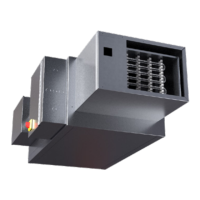
Figure 1. Fan Powered Terminal Unit with Electric Heater
Figure 2. Single Duct Terminal Unit with Electric Heater
CAUTION: ELECTRIC SHOCK HAZARD
1. Turn off power before servicing unit.
2. Do not operate unit without control cover.