6
SL2
Assembling and Installing SL2 (continued)
It is vitally important for correct operation of SL2 that the
Upper Cabinets are located properly on the Lower
Cabinets, that the Pins are in place and that the two
cabinets only touch via the spacers.
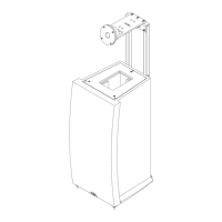
The alignment of the Tweeter within the Upper Cabinets can
be adjusted via either the two bolts connecting the Tweeter
Suspension Assembly to the Plinth or the four screws that
attach the Tweeter Adjustment Panel around the front face
of the Tweeter. If the four adjustment panel bolts are
loosened they should be re-tightened as securely as
possible. As well as being adjusted to sit centrally when
viewed from the front, and flush with the front panel, the
Tweeter must oscillate freely without touching any part of
either cabinet.
Finally fit a Grille to each SL2 by aligning it with the top of
the Lower Cabinet before pushing it gently against the
fixing tape on the Upper Cabinet. The lower edge of the
Grille should not touch the Lower Cabinet. The card
spacing jig packed with this manual can be used to support
the bottom edge of the Grille as it is fitted. Seen from the
side, the Grille should continue the curved form of the
front of the Lower Cabinet.
6.6 Connection
If the loudspeakers are to be used with Naim amplification,
use only Naim loudspeaker cable. Cable lengths to both
loudspeakers should be equal and be between 3.5 metres
and 20 metres (11.5ft and 66ft). Your local retailer will be
able to make up cables of the appropriate length.
If the SL2 is to be used in an active system, speaker
cables with their custom Naim plugs should be connected
to the appropriate input sockets on the back of the
Tweeter Suspension Arm (HF) and Upper Cabinet (LF).
Ensure that each positive plug - identified by a rib on the
side of the cable and a tag marked “pos” on the side of
the connector body - is inserted to the red input sockets.
If the SL2 is to be used in a passive system, the Passive
Crossover Units must be mounted to the back of each
Lower Cabinet. Screws and decoupling grommets are
supplied in the pack that contains the passive crossovers.
Tighten the screws so that the screw heads just touch the
decoupling grommets without compressing them.
The output cables from the Passive Crossover Units must
be connected to the input sockets on the back of the
speaker, the longer cable to the sockets on the back of
each Tweeter Suspension Assembly and the shorter cable
to the sockets on each Upper Cabinet. The cables should
be dressed such that they do not touch any other SL2
component and such that the output plugs align naturally
with input sockets. Stress in the cables will interfere with
the decoupling between SL2 components.
Finally the amplifier output speaker cables, with their
custom Naim plugs, should be connected to the input
sockets on the back of the Passive Crossover Units.
Ensure that each positive plug - identified by a rib on the
side of the cable and a tag marked “pos” on the side of
the connector body - is inserted to the red input sockets.