naishkites.com naishkites.com
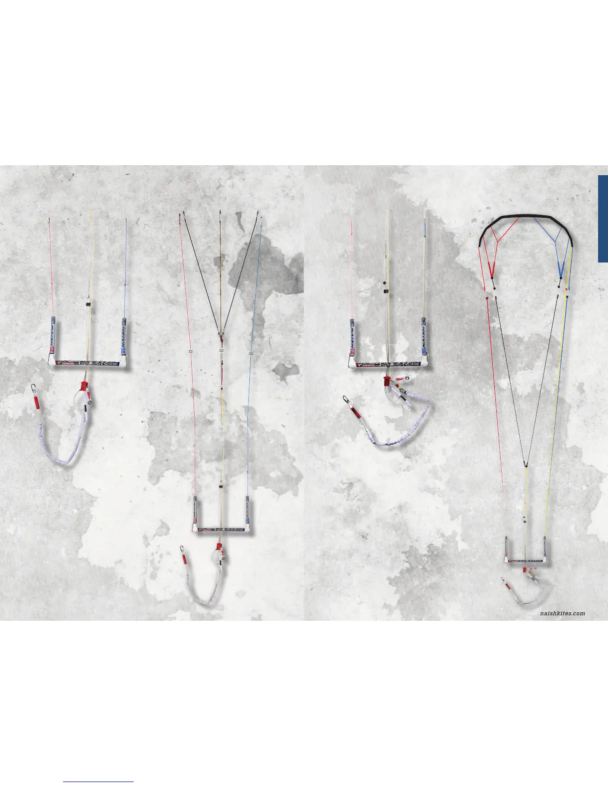
3. Assembling the Bar and Lines
The Shift System Drawing of Entire Shift System
3. Assembling the Bar and Lines
The Universal System Drawing of Entire Universal System
Your new Universal Control System is a plug and play
device; it comes completely assembled and ready to
use. Below is a diagram of the system and descriptions
of each line and its function.
A) Control bar
B) Leader Lines
C) Vario bar length adjuster tab
D) Handle pass leash
E) Smart Loop
F) Chicken finger
G) Trim line (Universal System)
H) Sliding stopper
I) Fixed stopper
J) Flagging line (yellow)
K) Universal line cluster
L) Colored back lines
M) Grey Front lines- attach to leading edge of kite
N) Bridle lines
O) Bridle pulley
P) LWR line (optional)
Your new Shift System is a plug and play device. It
come completely assembled and ready to use. These
are diagrams of the Shift System and descriptions of
each line and its function.
A) Control bar
B) Leader Lines
C) Vario bar length adjuster tab
D) Handle pass leash
E) Attachment loop
F) Smart Loop
G) Chicken finger
H) Trim line (Shift System)
I) Sliding stopper
J) Shift Line yellow bungee
K) Grey Front lines- attach to leading edge of kite
L) Shift Line yellow- attached on kite (not shown)
M) Y connector with pigtails for grey control lines to
attach to
N) Shift Line- yellow spectra line
O) Colored back lines
A
B B
C C
D
F
G
H
I
J
KK
O O
N
M
A
C C
D
E
F
G
H
I
N
L
O
K
J
M
P
A
B B
C
C
D
F
G
H
I
A
C C
D
E
F
G
H
I
E
E
B B
B B
M M
N
L
J
6 7
English