14 15naish.com
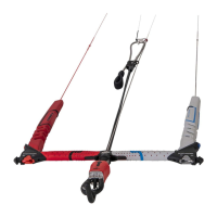
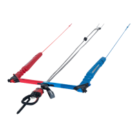
TORQUE 2 CONTROL SYSYEM
SENSE CONTROL SYSTEM
ADJUSTING TORQUE 2 BAR STEERING (REAR) FLYING LINES
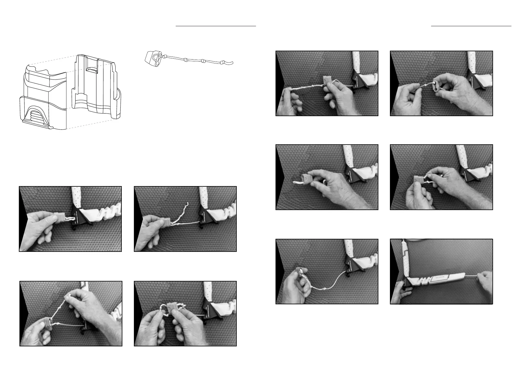
1 - Locking Cavity
2 - Locking Recess
3 - Adjusting Cavity
Repositioning the knots found inside the
bar/line adjuster changes the length of the
steering (rear) ying lines.
Knot A: Decreases the length of the
steering (rear) ying lines.
Knot B: Naish control systems are
delivered in the Knot B position.
Knot C: Increases the length of the
steering (rear) ying lines.
Knot D: Securing knot for the
Knot C position.
WARNING: Do not use Knot D position in
the locking cavity.
2
B
1
A
3
C
D
Pull the bar/line adjuster out from the bar end. Pull the end of leader line out from the Adjusting
Cavity (3).
Pull the knot out of the Locking Recess (2). Pull the leader line out through the bottom of the
Adjusting Cavity (3).
1
3
2
4
TORQUE 2 CONTROL SYSTEM
ADJUSTING TORQUE BAR STEERING (REAR) FLYING LINES (CONTINUED)
Pull the knot out of the Locking Cavity (1). Adjust the leader line to the desired knot using the
Adjusting Cavity (3).
Lock the desired knot securely in position using the
Locking Cavity (1).
Feed the end of the leader line back through the
Adjusting Cavity (3).
Lock the following knot securely in position using the
Locking Recess (2) and insert excess line into the
Adjusting Cavity (3).
IMPORTANT: Repeat this procedure on the
opposite bar end so the leader line length adjustment is
done exactly the same on both sides.
Reinstall bar/line adjuster by pushing it back into the
bar end, while pulling leader line above the oater to
remove any slack as shown.
5
7
9
6
8
10