
L
lgomezJul 29, 2025
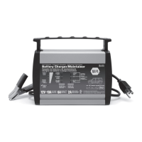
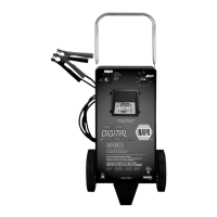
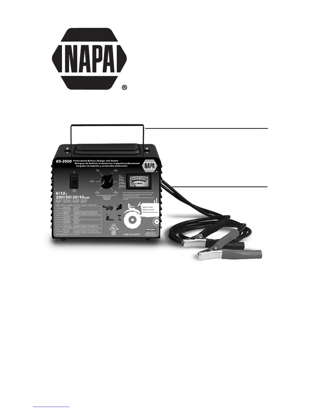
What to do if there is no reading on the ammeter of Napa Battery Charger?
- GgwoodsJul 29, 2025
If the Napa Battery Charger's ammeter shows no reading, several factors could be at play. First, ensure the charger is properly plugged into a functioning AC outlet and that the outlet has power by checking the fuse or circuit breaker. Next, verify that the clips are making a solid connection to the battery and frame, ensuring the connection points are clean and rocking the clips for better contact. Also, check that the connections are not reversed; if they are, unplug the charger and reverse the clips. Lastly, the battery itself might be defective and unable to accept a charge, in which case you should have it checked.