The
~
patturm
ilu&IMted
are
adjustable, wfthln
limtts
, bolh vertically and
hOriz:ontally (see
AOJUS1"MENTS
: Aiming
1he
Seams
for~
adf.JSlmttnt
ptoce<kJres)
Sdtings
Clf1
be
qOOe
e.rickaJ
.
~
Shown
herofn
are
typla!l ilfld
Mil
not apply to
all
cases
. Always test the
COYeNJge
p.cdtem attBr the
llnl
is instllfied
{see
lUTlNQ
l'tff:
CO'IERAGf:
AR
t:A)
.
NOTE
: N
the
standard
Ieos
docs
f'lOI
sull
the
epp6cation.,
sefed e reptacementfrom
NAf'CO's
l.en$
&ric
{
9W
OftOEFQ
NG
INFO
fUICAtlON
).
SflQhtly
IOOser'lltle
Ions
damping screws insida
the
front
00\lef
and
&fide
rut
the
IM$
.
Then
side
in the replacement lens wflh
grooved
side
facing
11wcY'd
,
make
the
req:..Krcd
adjustl"ntJr.ts
and
tigttten
tha
clamping screws j
ust
enough
to
stKU"e
the
'
~MS
.
Do
nor
cvertigh!en!
r---··
. .
.. ..
--
--
-- --
----·-···--·
··
-----
------
j
I"'
~
(h)
:):f?G50
~r,EF.Rr~
!
..........
....
.................
....
____
__j
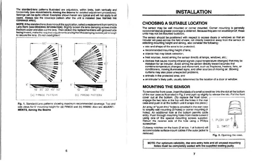
Fig.
1.
Standard·U!!lS pw.terns showing maximum
recommended
cov«age
.
Top
orv::1
sidG
vtcws
for
s·
mount§')g
height
tor
(e) PIR600
and
(b)
P1A680
. Also
see
AD
J
US
T·
MEMTS, Aimi
ng
1he
Seams
6
INSTALLATION
CHOOSING
A SUITABLE LOCATION
The
sensor
may
be
wait
moont8d
or corner mounted.
Comer
roounling is
g~
recommended
as
greater~
is obtained.
Because
!hey
are
not
weatbef'proof. these
units
may
not
be
mounted
0\Jidoofs.
llte
RnSor
should
be
positioned with
respect
to accen
do
ors
or
windows
so
that
an
iniNder
will
pass
across
the
rieJd
d view, not
C~rec!ly
toward
Of
r;way
from
the
sensor
.
In
seloct>'9
mounting heigh!
and
""'*'<~
-
-
...-
...
fcboing
:
• size and shepe
of
the
srea to
be
prowctcd;
•
recommeooed
mounting
h6Qht
ollens-:
• objeCts
~
rnBf block
~e!ection
;
•
he
a:.
scuCbs. Avoid Biming
the
sensor directly at lamps, windows, etc.;
• devices that
cause
mcr.AnQ
Infrared
Signals
(
r<Wid
temperatl68
c:h<lnges)
that
may
be
miStaken
for
en
lntrud~
.
AvOd aiming
the
sensor
dncUy
toward
sources
thsl
con'iJine
temperan..-e
,
c:hanges
and
M'10\191'Tl8nt
, s
uch
as
fireplares, hee\tlrs,
tans
, air
c::oodiOoners
, moving
i&Jminated
signs,
a.'"ld
other sources
of
moving air.
BSO
wing
curtaris
may
also
pose
unexpede<t problems.
• animals in the protected area; antt
•
an
R"ltruder's
tik8!y
path
, usually dtrtetmined
by
the
loc:<:lt!on
of
a
door
or
window.
MOUNTING
THE
SENSOR
To remove
!he
front C<Ner, Insert
1t.e
blade
of
a
smaJI
saewdtivel"
InfO
the
51o
t at !he bottom
of
the
rear
case
as
ihustratcd
1n
Ag
. 2
and~
up
Sli:Qhfi"i
to
releasttlhe
tab
.
Pulf
the
front
~~at~~~~=:.e:~the~
r-----
---
---·-····--
-
cese
and
push in at
ttw
bottom
un<ll
it sneps
int
o place.} I
{C.~
~=~:~~~~~{:
~~~\
holes). An Ad(ftJona! hole at
IJlc
bottom
permits
cab!&
;
t:_...;f~:~~
entry. Puoh
111tough
<l1CI\¥>Ilng
holes !tom lnsKle
.,.,._.
; I
using
one
ol
the
special mounting sCfews
St;JpJ'ecJ
l
~
PVSII UF'
i
~
~
=..:..:.
reverse side
ot
the
hole
USfi9
a Philli
ps
· j
Cutawaynotchesontheback{2attop
, 1
atbotlom)w
il
~-
TY..,ST
\.
d.
I
a£:COmmoc1crte
surtace-mount cabftls it the outar jacket
ts
_
__j
removed.
-
~~
-
2.
Openng
the
case
.
~--
-------
··--
------------
-------------------~
~
NOTE:
For
optim
um retit:b
8Jty,
the
wi
t'lt
-entry
hafe and all unU&ed
moun
-
~
---~-!
L_
__
n
~
~be
com
p~ety
saale<t with
the
Sliupptliect
s
aa
Un
g
pu
tty
.
~
~
7



 To Next Page
 Loading...