3
A
50
400
400
110/55 mm
X
100
100
400
500
500
250
250
400
125
125
500
X
100
100
400
500
500
250
250
400
125
125
500
100
100
400
A
50
400
400
110/55 mm
X
100
100
400
500
500
250
250
400
125
125
500
400
400
110/55 mm
X
100
100
400
500
500
250
250
400
125
125
500
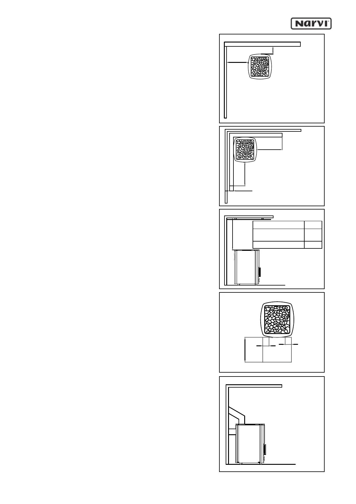
4. For brick walls, a ventilation gap of 50 mm between
the vertical surfaces of the sauna heater and the wall is
sufcient. (Figure 4)
The dimension A is determined based on the safety
method used for wooden surfaces:
- without protection 500 mm
- single-light protection 250 mm
- double-light protection 125 mm
5. Brickwork of 55 mm that is open at the edges and
at least 30 mm clear of the surface to be protected
corresponds to single-light protection. Brickwork which
is 110 mm of the surface to be protected corresponds
to double-light protection. (Figure 5)
Protection of the ceiling:
When the distance from the upper surface of the sauna
heater to the ceiling is at least 1200 mm no special
protection of the ceiling is necessary. If the distance
is less than 1200 mm the protection method for the
ceiling is selected from paragraphs 1-3. (Figure 6)
Protection of the oor in front of the sauna heater:
Floors made of inammable material must be protected
with a metal plate that reaches at least 100 mm to both
sides of the sauna heater and 400 mm in front.
There must be 1000 mm free room in front of the hatch.
(Figure 7)
INSTALLATION OF THE SAUNA HEATER
In all our sauna heater models there is the smoke
opening in the connective ue on top and rear of the
rebox. Block the unused opening with the cover plate
included in the delivery. Also included in the delivery
is a 200 mm ue pipe connector for connection of the
sauna wood-burning heater to a rear ue pipe. When
connecting the sauna wood-burning heater to the ue
from the top of the wood-burning heater, always use
KOTA chimney pipes or KOTA chimney ues.
Do not install the ue adapter pipe too deeply into the
chimney ue, as this will reduce the ue draw. The gap
between the ue adapter pipe and the chimney ue
must be insulated e.g. with mineral wool. The sauna
wood-burning heater comes tted with adjustable legs
to assist accurate installation. In connection with the
sauna wood-burning heater installation, ensure that
the wood-burning heater stands rmly on its base and
that all of the safety clearances mentioned in these
instructions have been observed correctly.
Figure 4
Figure 6
Figure 7
Figure 5
Figure 8
X mm
The ceiling without
protection
1200
Single-light protection 900
 Loading...