Do you have a question about the Nat NPX136D Series and is the answer not in the manual?
Provides an overview of the content covered in Section 1 of the manual.
Details the NPX136D panel mount P25 VHF transceiver and its suitability for single mission users.
Highlights key capabilities such as frequency range, operating modes, scan function, and controls.
Lists electrical and performance parameters for power, current, and frequency.
Provides detailed specifications for the main receiver's sensitivity, rejection, and audio output.
Specifies parameters for the guard receiver, noting its exception to the main receiver specs.
Details transmitter specifications including output power, stability, deviation, and audio response.
Lists dimensions, weight, and connector types for the transceiver unit.
Outlines operating conditions including temperature, altitude, humidity, and shock resistance.
Explains how the first digit of the unit suffix indicates the lighting power used.
Describes how the second digit of the unit suffix denotes installed special options.
Notes that the third digit of the unit suffix is currently not assigned.
Outlines the content of Section 2, covering unpacking, installation, and checks.
Provides instructions for carefully unpacking and inspecting the radio for shipping damage.
Details the 2-year warranty terms, conditions, and voiding clauses.
States that maintenance is 'on condition' only and no periodic maintenance is required.
Guidance on proper cable bundling, placement, and use of shielded cable.
Warns about potential audio degradation from incorrect wiring and shielding.
Specifies electrical grounding requirements for the radio case to minimize interference.
Details wire selection, shielding, termination, and service loop requirements.
Provides guidelines for antenna placement, mounting, and separation to ensure performance.
Instructions for physically mounting the transceiver using Dzus rail or equivalent.
Procedures for verifying voltage, resistance, and power-on functionality.
Specific checks for +28 Vdc power and continuity to ground.
Steps to confirm correct operation of controls, display, and transmit/receive functions.
Procedure to identify and document any interference caused by the radio to aircraft systems.
Introduces Section 3, covering operational procedures for the NPX136D transceivers.
Provides background on the NPX136D, its features, frequency range, and modes.
Discusses additional features like alphanumeric labeling and built-in operator help.
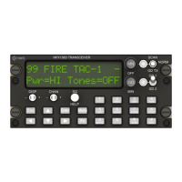
Describes the power-up sequence, software version display, and module status.
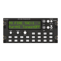
Details all front panel buttons, knobs, and switches for operating the transceiver.
Explanation of information shown on the upper and lower display rows.
Details on channel numbering, tone/squelch, modulation, and scan flags.
Formats for displaying receive, transmit, simplex, zone, and talk group data.
Methods for selecting channels via front panel or remote switch.
How to navigate and select different zones for channel management.
Access to general NPX136D settings like brightness, power, and squelch.
Adjusts display brightness levels for off and on panel light conditions.
Sets transmit power to Low, High, or Per Channel.
Selects between Simplex or Duplex (repeater) operating modes.
Configures analog tone types and settings (On, Off, TxOnly).
Sets digital squelch mode to Monitor or Per Channel.
Defines the channel the radio tunes to after power up.
Adjusts noise squelch levels for analog channels.
Customizes display options like CTCSS, Talk Group IDs, and power-up screens.
Selects between Numeric or Alphanumeric channel numbering.
Access to edit channels, guards, zones, and scan lists.
Allows modification of parameters for main transceiver channels.
Fields for setting receive/transmit frequencies and available frequency increments.
Allows setting a 9-character alphanumeric name for a channel.
Sets the channel modulation type to Wide, Narrow Analog, or Digital.
Sets the channel's transmit power level to Hi or Lo.
Assigns a channel to a specific zone, all zones, or no zone.
Allows editing the channel label when master edit mode is on.
Sets the type of receive subaudible tone for analog channels.
Sets the specific receive subaudible tone or code for analog channels.
Sets the type of transmit subaudible tone for analog channels.
Sets the specific transmit subaudible tone or code for analog channels.
Sets the digital squelch mode (Monitor, Normal, Select) for receive.
Sets the Network Access Code (NAC) for digital channels.
Displays the receive talk group ID for digital channels.
Sets the Network Access Code (NAC) for transmit on digital channels.
Displays the transmit talk group ID for digital channels.
Allows editing of guard channel parameters, which are always locked.
Enables/disables zones, edits zone names, and manages channel assignments.
Option to enable or disable the zone feature.
Allows changing the name of the current zone.
Shows channels assigned to each zone and allows adding/removing channels.
Settings for scan modes, priority channels, and scan list management.
Sets the scan mode to List, Priority, or List+Priority.
Specifies the priority channel for scanning.
Allows reviewing, adding, or deleting channels from the scan list.
Enables editing of locked channels and channel numbers after password entry.
Advanced settings for qualified technicians, including user ID and system parameters.
Access to diagnostic tests for switches, display, and power input.
Controls the visibility of the noise squelch field in the settings menu.
Enables or disables the guard receiver module.
Sets the minimum volume allowed for the guard receiver.
Adjusts the level of the sidetone audio output.
Sets the maximum duration for transmitter keying.
Defines the interval for checking priority channels during scanning.
Sets the total number of available channels on the transceiver.
Facilitates copying channel and configuration data between units.
Displays MCU application revision and software build dates.
Allows transmission of DTMF sequences for analog channels.
Entry and saving of new DTMF numbers.
Access to recently transmitted DTMF sequences.
Retrieval of stored DTMF numbers and names.
Indicates that no call menu is implemented for digital channels.
List of Continuous Tone-Coded Squelch System frequencies and codes.
List of Continuous Digital-Coded Squelch System codes.
| Brand | Nat |
|---|---|
| Model | NPX136D Series |
| Category | Transceiver |
| Language | English |