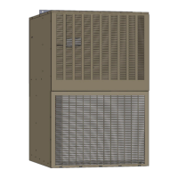
Do you have a question about the National Comfort Products Comfort Pack U Series and is the answer not in the manual?
| Refrigerant | R-410A |
|---|---|
| Voltage | 208/230V |
| Phase | 1 |
| Unit Weight | Varies by model |
| Dimensions | Varies by model |
| Sound Level | 72 dB |
Defines danger levels for compliance with safety protocols.
Covers warnings related to grounding, high voltage, and wiring integrity.
Covers warnings about gas, water damage, installation, and improper operation.
Instructions for removing shipping bolts and preparing the cabinet.
Requirements for unit placement and wall mounting.
Details on connecting the primary and secondary drain lines and trap.
Instructions for installing the unit within the wall and sealing.
Specifies minimum distances from combustible materials and other units.
Step-by-step guide for installing the secondary drain trap.
Guidelines for preparing the wall opening and ensuring proper flashing.
Ensuring adequate airflow and avoiding recirculation issues.
Requirement for 29" clearance for inside service panel access.
Specifies clearances for direct-vented installations per ANSI Z223.1/NFPA 54.
Important notes regarding venting installation and potential issues.
Guidelines for power supply, wiring, and grounding.
Recommendations for thermostat placement and low-voltage wiring.
Illustrates the high voltage connections for the unit.
Identifies key components and terminals on the DSI control board.
Details on low voltage common, secondary, and fuse connections.
Details on gas valve settings, BTU input/output, and temperature rise.
Step-by-step description of the heating cycle operation.
Explains various fault conditions and lockout states.
Procedures for adjusting the unit for high altitude installations.
Guidelines for gas pipe sizing, support, and connections.
Procedures for testing gas supply piping pressure.
Step-by-step instructions for measuring and adjusting gas valve outlet pressure.
Illustrates gas connection points and components.
Describes the direct spark ignition process and its operating sequence.
Explains the role and operation of the combustion air proving switch.
Details the auto-reset limit control and its protective functions.
A comprehensive checklist before initiating the start-up process.
Critical safety instructions to follow before operating the unit.
Steps for operating the unit and sequence of heating activation.
Procedure for safely shutting off the gas supply to the appliance.
Verifications to perform after the initial start-up.
Guidance on maintaining the cooling chassis and its components.
Recommended intervals for checking filters, cleaning components, and inspecting the unit.
Procedures for inspecting the heat exchanger for cracks or holes.
Step-by-step instructions for removing, cleaning, and reinstalling the burner assembly.
Instructions for servicing the burner orifice and igniter.
Guidance on cleaning the flame sensor.
Procedures for maintaining the venter motor and wheel assembly.
Explains the function of limit controls and gas valves.
Details the operation and troubleshooting of pressure and rollout switches.
Interpreting LED signals for diagnosing abnormal conditions.
Tables detailing cooling and heating performance data by model.
Electrical characteristics such as voltage, amps, and MCA for each model.
Lists available optional accessories for the unit.
Instructions for measuring supply and return air temperatures for temperature rise.
Formula and reference to airflow data for calculating CFM.
Explains GREEN and YELLOW LED indicators for operational status and faults.
Guidelines for field control wiring length, gauge, and testing.
Part numbers for various cabinet and furnace components.
Part numbers for components specific to chassis models.
Outlines the terms, duration, and limitations of the product warranty.
Steps required for customers to initiate and process a warranty claim.
 Loading...