Appendix A Device-Specific Information
M Series User Manual A-76 ni.com
To measure a floating signal source, move the switch to the FS position. To
measure a ground-referenced signal source, move the switch to the GS
position. Figure A-31 shows the AI 0 BNC and corresponding FS/GS
switch on the top panel of the USB-6251 BNC.
Figure A-31. FS/GS Switch
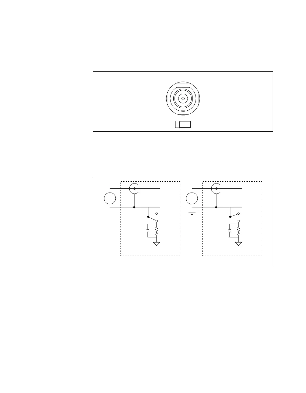
Figure A-32 shows the analog input circuitry on the USB-6251 BNC.
When the switch is in the FS position, AI x – is grounded through a 0.1 µF
capacitor in parallel with a 5 kΩ resistor.
Figure A-32. Analog Input Circuitry
Single-Ended Signals
For each BNC connector that you use for two single-ended channels, set the
source type switch to the GS position. This setting disconnects the built-in
ground reference resistor from the negative terminal of the BNC connector,
allowing the connector to be used as a single-ended channel, as shown in
Figure A-33.
FS GS
AI 0
AI
x
+
AI
x
–
GS
0.1 µF
5 kΩ
AI GND
FS
+
–
USB-62
xx
Device
Floating Source
AI
x
+
AI
x
–
GS
0.1 µF
5 kΩ
AI GND
FS
+
–
USB-62
xx
Device
Grounded Source
 Loading...