EasyManua.ls Logo

Navien NCB-190/060H User Manual

Navien NCB-190/060H
145 pages
To Next Page IconTo Next Page
Page #1 background imageLoading...
Page #1 background image
WARNING
If the information in these instructions is not followed exactly, a fire or explosion may
result, causing property damage, personal injury, or death.
Do not store or use gasoline or other flammable vapors and liquids in the vicinity of this or any
other appliance.
WHAT TO DO IF YOU SMELL GAS
Do not try to light any appliance.
Do not touch any electrical switch; do not use any phone in your building.
Immediately call your gas supplier from a neighbor’s phone. Follow the gas suppliers instructions.
If you cannot reach your gas supplier, call the fire department.
Installation and service must be performed by a qualified installer, service agency or the gas
supplier.
The installation must conform with local codes or, in the absence of local codes, the National Fuel
Gas Code, ANSI Z223.1/NFPA 54 and/or CSA B149.1, Natural Gas and Propane Installation Code.
H
NSF/ANSI 372
Keep this manual near this boiler for future reference
whenever maintenance or service is required.
* The wetted surface of this product contacted by consumable water
contains less than one quarter of one percent (0.25%) of lead by weight.
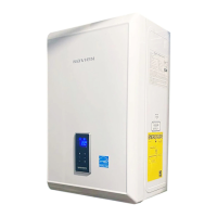
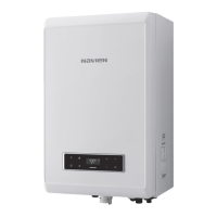
Installation & Operation Manual
NCB-H Condensing Combi-Boilers
Model
NCB-190/060H
NCB-190/080H
NCB-240/110H
NCB-240/130H
NCB-250/150H

Table of Contents

Other manuals for Navien NCB-190/060H

Questions and Answers:

Navien NCB-190/060H Specifications

General IconGeneral
BrandNavien
ModelNCB-190/060H
CategoryBoiler
LanguageEnglish

Summary

Massachusetts Installation Requirements

Notice Before Installation

Mandatory installation by a licensed professional according to state codes.

Important Massachusetts Requirements

Specific rules for vented gas equipment, including CO detectors and signage.

About the Navien NCB-H Boiler

1.1 Included Items

List of components found in the boiler packaging upon delivery.

1.2 Accessories

Details of optional accessories available for purchase for the boiler.

About the Navien NCB-H Boiler

1.3 Specifications

Technical specifications for space heating and domestic hot water performance.

About the Navien NCB-H Boiler

1.5 Dimensions

Physical dimensions of the boiler unit and connection sizes.

1.6 Rating Plate

Information on the boiler's rating plate, including gas type and electrical specifications.

Boiler Installation Procedures

2.1 Choosing an Installation Location

Guidelines for selecting a suitable installation location considering utilities and clearances.

Humidity and Contact with Water

Precautions to prevent moisture damage to ignition components.

Adequate Drainage

Requirements for condensate drainage to prevent water damage and voiding warranty.

Boiler Installation Procedures

Adequate Installation Clearances

Minimum clearances required around the boiler for service and ventilation.

Boiler Installation Procedures

2.2 Mounting the Boiler to the Wall

Instructions for securely mounting the boiler unit to a wall using the provided bracket.

Clean, Debris and Chemical-free Combustion Air

Guidelines for ensuring clean combustion air and avoiding corrosive contaminants.

System Piping Installation Guide

3.1 Installing a Space Heating System

Steps and guidelines for installing the space heating system piping.

System Piping Installation Guide

3.1.2 Essential Elements in a Space Heating System

Key components for space heating, including LWCO, system pressure, and oxygen elimination.

System Piping Installation Guide

Expansion Tank

Requirement for an expansion tank to prevent over-pressurization in the heating system.

Isolation Valves and Unions

Recommendations for using isolation valves and unions for serviceability and flow.

System Piping Installation Guide

3.2 Installing a Domestic Hot Water (DHW) System

Procedure for installing the DHW system, focusing on on-demand hot water.

Scald Hazard

Warning about the risk of scalding from high hot water temperatures.

System Piping Installation Guide

3.3 Connecting the Condensate Drain

Guidelines for connecting and disposing of acidic condensate from the boiler.

System Piping Installation Guide

3.4 Filling the System

Steps for filling the boiler with water and purging air before operation.

System Piping Installation Guide

3.5 Testing the Water System

Procedure for performing a fill test to ensure the water system is installed correctly.

System Piping Installation Guide

3.6 Considerations for System Applications

Guidelines for system piping applications, including air removal and expansion tanks.

System Piping Installation Guide

Air Handler Interface

How the boiler controls an air handler unit via a thermostat.

System Piping Installation Guide

Configuring a Zone System

Steps to configure the boiler for up to 3 zones using zone valves or pumps.

System Piping Installation Guide

3.6.3 System Application - Zone System with Pumps (Primary/Secondary Piping)

Diagram and explanation for a zone system using pumps with primary/secondary piping.

System Piping Installation Guide

3.6.4 System Application - Zone System with Zone Valves (Primary/Secondary Piping)

Diagram for a zone system using zone valves with primary/secondary piping.

System Piping Installation Guide

3.6.5 System Application - Air Handler System

Diagram illustrating the system application for an air handler.

System Piping Installation Guide

3.6.6 System Application - Air Handler System with RS-485 Communication

Diagram for air handler system with RS-485 communication via thermostat.

System Piping Installation Guide

3.6.8 External Recirculation with Dedicated Return Line (Always On, Weekly, Intelligent)

Configuration for external recirculation with dedicated return line for DHW.

System Piping Installation Guide

3.6.9 External Recirculation with HotButton and Dedicated Return Line (HotButton, Aquastat)

Setup for external recirculation using HotButton or Aquastat with a dedicated return line.

Electrical Connections Overview

3.7.1 Accessing the Terminal Strips

Instructions for safely accessing the boiler's terminal strips for wiring.

3.7.2 Wiring Diagram - External LWCO

Wiring diagram for connecting an external Low Water Cut Off (LWCO) device.

System Piping Installation Guide

3.7.3 Wiring Diagram - Zone Pump System

Wiring diagram for operating a heating system with up to 3 zones using zone pumps.

System Piping Installation Guide

3.7.4 Wiring Diagram - Zone Pump System with DHW Recirculation

Wiring diagram for 3-zone heating and DHW recirculation using zone pumps.

System Piping Installation Guide

3.7.5 Wiring Diagram - Zone Valve System

Wiring diagram for a heating system with up to 3 zones using zone valves.

System Piping Installation Guide

3.7.6 Wiring Diagram - the Navien SmartZone +

Wiring diagram for using the Navien SmartZone+ controller with NCB-H boilers.

System Piping Installation Guide

3.7.7 Wiring Diagram - Generic Zone System with Zone Valves

Wiring diagram for a generic zone system using zone valves.

3.7.8 Wiring Diagram - Generic Zone System with Zone Pumps

Wiring diagram for a generic zone system using zone pumps.

System Piping Installation Guide

3.7.9 Wiring Diagram - Air Handler

Wiring diagram for connecting the boiler to an air handler unit.

System Piping Installation Guide

Wiring Diagram - Optional Universal Temperature Sensors (for Supply/Return)

Diagram showing how to connect optional universal temperature sensors.

Gas Supply Connection Guide

WARNING

Crucial safety warnings regarding gas type, pressure, and connections.

Gas Supply Connection Recommendation

Recommendation for optimal gas supply by connecting the boiler first after the meter.

Gas Supply Connection Guide

CAUTION

Important cautions for installing shut-off valves and sediment traps in the gas line.

Gas Supply Connection Guide

LP Gas Piping Examples

Piping configurations for LP gas systems using single or multi-stage regulators.

2 Stage System with Multiple Regulators (Recommended)

Recommended piping setup for LP gas with a two-stage regulator system.

Single Regulator System

Piping configuration for an LP gas system using a single regulator.

Gas Supply Connection Guide

4.1 Gas Pipe Sizing Tables

Tables for determining correct gas pipe diameter based on length and capacity.

Gas Supply Connection Guide

4.2 Measuring the Inlet Gas Pressure

Procedure for measuring inlet gas pressure for natural gas and propane.

Combustion Air and Venting Guidelines

Additional Guidelines for Combustion Air

Recommendations for intake air piping and avoiding contaminated air sources.

Corrosive Contaminants

List of chemicals and compounds that can cause corrosion if present in combustion air.

Corrosive Sources

List of common locations and activities that may produce corrosive contaminants.

Combustion Air and Venting Guidelines

5.1 Venting the Boiler

Essential guidelines for proper boiler venting to ensure safety and performance.

Connecting the Pipe to the Vent Collar

Instructions for connecting vent pipe to the boiler's vent collar, emphasizing airtight seals.

Combustion Air and Venting Guidelines

5.2 About the Vent Installation Detector

Explanation of the Vent Installation Detector (VID) and its function in ensuring proper vent pipe insertion.

Combustion Air and Venting Guidelines

5.3 Selecting a Vent Type

Guidelines for selecting vent types, including direct and non-direct venting options.

Direct Venting

Guidelines for direct venting, including duct sizes and termination clearances.

Non-Direct Venting (Single Pipe)

Considerations for non-direct venting, including potential backdraft and freezing issues.

Combustion Air and Venting Guidelines

5.4 Selecting Vent Pipe Materials

Approved vent pipe materials for USA and Canada, and prohibited materials.

Combustion Air and Venting Guidelines

5.5 Measuring Vent Length

Guidance on calculating maximum vent lengths, considering elbows and termination kits.

Combustion Air and Venting Guidelines

5.6 Terminating the Vent

Approved vent termination kits for PVC and polypropylene materials.

PVC vent terminations

Approved PVC vent termination kits for the appliance.

polypropylene vent terminations

Approved polypropylene vent termination kits for the appliance.

Combustion Air and Venting Guidelines

Indoor Boiler Installation Venting Examples

Examples of indoor venting configurations for boilers.

Two-Pipe Sidewall Venting

Example of a two-pipe sidewall venting configuration.

Combustion Air and Venting Guidelines

Concentric Sidewall Venting

Description and clearance requirements for concentric sidewall venting.

Concentric Vertical Venting

Description and clearance requirements for concentric vertical venting.

DIP Switch Configuration

6.1 DIP Switch 1 (6 switch unit)

Configuration settings for DIP Switch 1 related to operation status.

6.2 Dip Switch 2 (8 switch unit)

Configuration settings for DIP Switch 2 for gas type, altitude, and country.

Power Supply Connection

WARNING

Critical safety warnings about electrical connections and potential hazards.

When connecting the power supply, follow these guidelines:

Step-by-step instructions and guidelines for connecting the boiler's power supply.

Cascade System Installation

8.1 Connecting Water Supplies

Options for connecting water supplies in a cascade system with multiple units.

Cascade System Installation

8.2 Cascade System - Recirculation System Application Example

Example of recirculation system setup in a cascade configuration with return line.

Cascade System Installation

If Recirculation Return Line Is Not Installed

Procedure for cascade recirculation without a dedicated return line.

Cascade System Installation

8.3 Connecting the Communication Cables

Instructions for connecting communication cables between units in a cascade system.

Common Vent System Installation

9.1 About the Common Vent System

Overview of the common vent system for multiple boilers and water heaters.

9.1.1 Guidelines for a Common Vent System

Essential guidelines for safe and correct installation of a common vent system.

Common Vent System Installation

Adequate Installation Clearances

Required clearances for common vent system installations.

Common Vent System Installation

Cutting and Assembling Common Vent System Components

Guidelines for cutting and assembling common vent system components.

Selecting Vent Pipe Materials

Approved vent pipe materials for common vent systems, adhering to standards.

Common Vent System Installation

Connecting Pipes with Cement

Instructions for connecting vent pipes using solvent cement and primer.

Common Vent System Installation

9.1.2 Determining the Length of a Common Vent System

Method for calculating total common vent length based on BTU input and physical layout.

Common Vent System Installation

Example of a Typical Installation (Direct Vent Only)

Illustration of a typical common vent system installation for a cascade setup.

9.2 Navien Common Vent Collar Kit (Back-draft Damper)

Description and function of the Navien Common Vent Collar Kit with backdraft damper.

Common Vent System Installation

9.3 Starting the Common Vent System

Steps to start the common vent system, including collar kit assembly.

9.3.1 Common Vent Collar Kit Assembly

Instructions for assembling the common vent collar kit onto the boiler.

Common Vent System Installation

9.3.2 Connecting the Pipe to the Common Vent Collar Kit

Procedure for connecting vent pipes to the common vent collar, ensuring proper insertion and sealing.

Common Vent System Installation

9.3.3 Assembling the Wye Joint

Instructions for assembling wye joints and reducers for common vent pipe connections.

Common Vent System Installation

9.4 Connecting and Terminating the Vent Pipe

Steps for connecting vent pipes and terminating the common vent system.

9.4.1 Connecting the Main Pipe Runs to Wye Joint or Wye Assembly

Connecting main vent pipes to the wye joint or assembly for the common vent.

9.4.2 Installing the System Termination

Examples of how to fit end caps, elbows, or tees at the end of common vent system piping.

Common Vent System Installation

9.5 Setting Up the Common Vent System

Procedure for setting up the common vent system type via the control panel.

9.6 Common Vent Termination Clearances

Clearance requirements for common vent termination based on installation type.

9.6.1 Direct Vent Application – Vertical Installation

Clearance requirements for vertical direct vent termination in common vent systems.

9.6.2 Venting Intake and Exhaust to Different Locations

Examples of venting intake and exhaust to separate locations for common vents.

Common Vent System Installation

9.6.3 Direct Vent Application – Horizontal Installation

Clearance requirements for horizontal direct vent termination in common vent systems.

9.7 Installing a Condensate Drain

Instructions for installing a condensate drain hose for the common vent system.

Common Vent System Installation

Condensate Drain Installation for Cascade Systems

Steps for forming a loop and installing a condensate drain hose for cascade systems.

Common Vent System Installation

9.8 Exhaust Vent Termination Clearances (For Direct Vent)

Clearance requirements for direct vent exhaust termination based on Canadian and US installations.

Common Vent System Installation

9.9 Maintenance

Procedure for checking the damper condition and maintaining the common vent collar kit.

Boiler Installation Checklist

Installing the boiler

Checklist items for proper boiler installation, clearances, and air supply.

Connecting the Gas Supply

Checklist items for correct gas supply connection, pressure, and leak testing.

Connecting the Domestic Water Supply

Checklist items for domestic water supply, including pressure, valves, and filter cleaning.

Boiler Installation Checklist

Connecting the Space Heating Piping

Checklist items for space heating piping, including filling, air removal, and expansion tank.

Connecting a Pressure Relief Valve

Checklist items for pressure relief valve installation, rating, and discharge tube.

Connecting the Condensate Drain

Checklist item for proper installation of the condensate drain line.

Venting the boiler

Checklist items for boiler venting, slope, support, and termination.

Boiler Installation Checklist

Venting the boiler (Continued)

Checklist items for vent termination height, makeup air, and total vent length.

Connecting the Power Supply

Checklist items for power supply connection, voltage, grounding, and switch installation.

PCB DIP switch setting (DIP SW 2, set of 8)

Checklist items for setting DIP Switch 2 for gas type and high temperature venting.

Operating the boiler

Checklist items for showing owner operation, filter cleaning, and emergency shut-off.

Boiler Operation Guide

11.1 Operating the Boiler for the First Time

Step-by-step instructions for the initial startup and operation of the boiler.

Boiler Operation Guide

11.2 Turning the Boiler On or Off

Instructions on how to turn the boiler on and off using the power button.

Boiler Operation Guide

11.3 Start-Up Wizard

Guide to completing the initial setup wizard for the boiler before first use.

11.4 Adjusting the Temperature

Procedure for adjusting the boiler's operating temperatures.

11.4.1 Adjusting the Space Heating Temperature

Procedure for adjusting the space heating supply and return water temperatures.

Boiler Operation Guide

11.4.2 Adjusting the DHW Temperature

Procedure for adjusting the domestic hot water (DHW) temperature setting.

Boiler Operation Guide

11.4.3 Resetting the Boiler

Instructions on how to reset the boiler to resolve operational problems or error messages.

11.5 Accessing Basic Menu Items

How to navigate and access basic menu options on the boiler's control panel.

11.5.1 Viewing Basic Information

How to view basic boiler information such as operation state and heat capacity.

Boiler Operation Guide

11.5.2 Setting the Space Heating Operation

Configuration of space heating operation parameters, including set points and outdoor reset.

11.5.3 Setting the DHW Operation

Configuration of domestic hot water (DHW) operation settings, including temperature and recirculation.

Boiler Operation Guide

Combi Pre-Heat Settings

Settings for the combi pre-heat feature to ensure quick DHW supply.

Boiler Operation Guide

External Recirculation Settings

Options for external recirculation settings, including modes like Intelligent and Weekly.

Boiler Operation Guide

11.5.4 Viewing Error History

How to view and interpret error codes and history displayed on the boiler panel.

11.5.5 Viewing Other System Information

Accessing miscellaneous system data and information via the menu.

Boiler Operation Guide

11.5.6 Setting the Display Options

Configuration of display settings such as language, temperature units, and backlight.

11.6 Accessing Advanced Menu Items

How to access and navigate advanced menu options for detailed settings.

11.6.1 Viewing Service Information

How to access and view service status information for the boiler.

Boiler Operation Guide

11.6.2 Viewing Input and Output Status

How to view the status of boiler inputs and outputs for system diagnosis.

Boiler Operation Guide

11.6.3 Setting the Operation Parameters

Detailed guide to setting operational parameters, requiring professional access.

Boiler Operation Guide

11.6.4 Configuring a Cascade System

Steps for configuring cascade system settings and managing units.

Boiler Operation Guide

11.6.5 Setting the External Connection

Procedure for viewing and configuring external network connections.

Boiler System Diagnosis

1. NaviLink Connect

Enabling or disabling remote control capabilities via NaviLink.

2. AHU Communication

Configuring AHU communication settings for use with NCB-H boilers.

Boiler Operation Guide

11.6.7 Setting the Special Operation Modes

Selecting and configuring special operating modes for the boiler.

11.6.8 Operating in Air Purge Mode

Instructions for operating the boiler in air purge mode for the heating system.

Boiler Operation Guide

11.7 Understanding Error Codes

A guide to understanding error codes and their potential remedies.

Appendixes and Conversions

12.1 Gas & High Altitude Conversion

Instructions for converting the boiler for propane gas or high altitude installation.

Appendixes and Conversions

Tools Required for Conversion

List of tools necessary for gas and high altitude conversion procedures.

Included Items in Conversion Kits

List of components included in the gas and high altitude conversion kits.

Orifice Size Information

Table showing orifice sizes for different models and gas types for conversion.

Conversion Procedure

Step-by-step procedure for performing gas and high altitude conversions.

Appendixes and Conversions

12.2 Wiring Diagram

Detailed wiring diagram of the NCB-H boiler's internal components and connections.

Appendixes and Conversions

12.3 Ladder Diagram

Ladder diagram illustrating the boiler's electrical control logic and system interconnections.

Appendixes and Conversions

12.4 Outdoor Temperature Sensor Installation

Installation guidelines for the outdoor temperature sensor.

12.5 Outdoor Reset Control Configuration

Information on configuring the Outdoor Reset Control for energy efficiency.

Component Assembly and Parts Lists

12.6.1 Case Assembly

Diagram and parts list for the boiler's case assembly.

Component Assembly and Parts Lists

12.6.2 Burner Assembly

Diagram and parts list for the boiler's burner assembly.

Component Assembly and Parts Lists

12.6.3 Waterway Assembly

Diagram and parts list for the boiler's waterway assembly components.

Component Assembly and Parts Lists

12.6.4 Fan (Gas) Assembly

Diagram and parts list for the boiler's fan (gas) assembly.

Getting Service and Support

Contact Technical Support

Information for contacting technical support for service and warranty issues.

Information to Have Ready for Support

Details required when contacting technical support for efficient assistance.

Related product manuals