hon
Condensate Outlet
Water
Floor drain
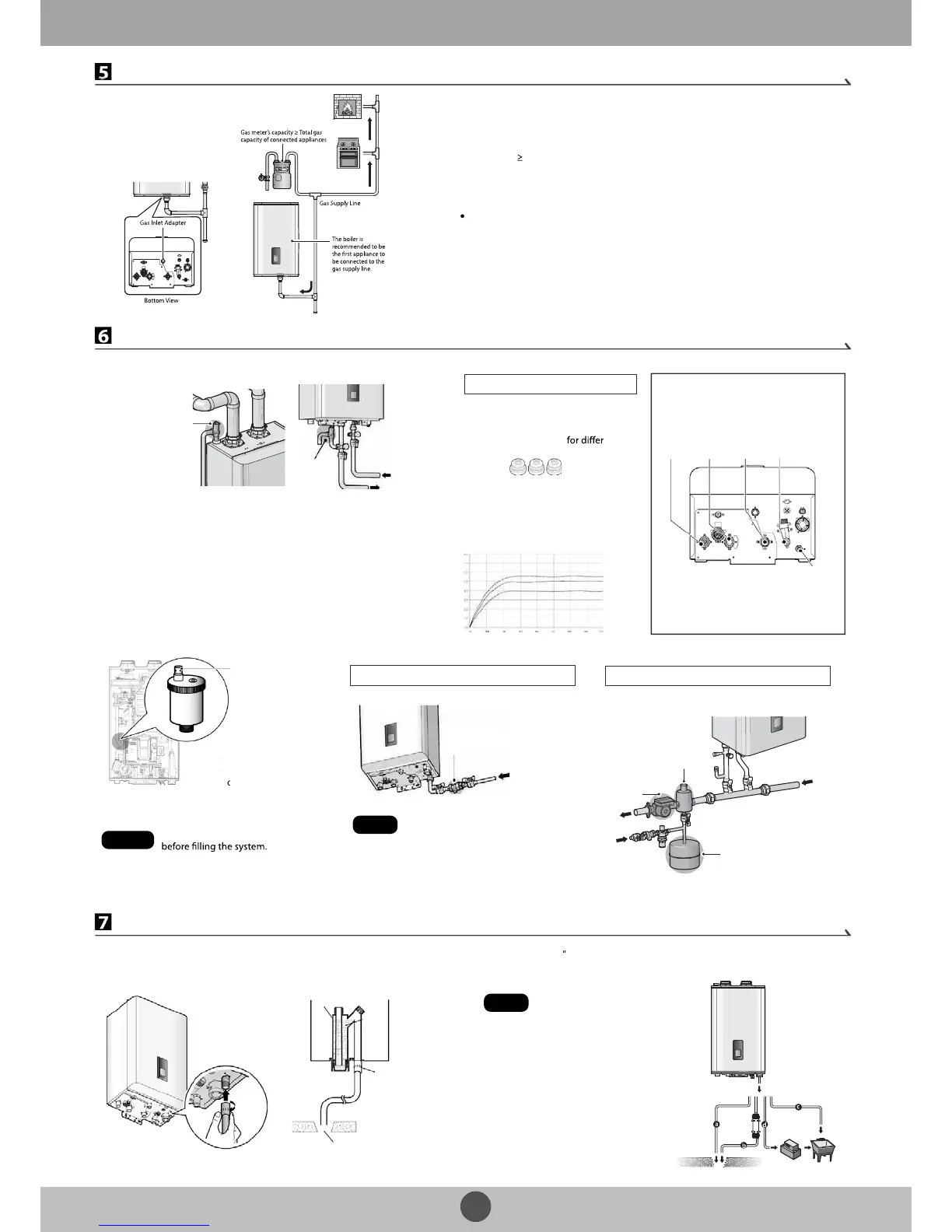
Example:
Gas meter
425 CFH
Boiler
195 CFH
+ Furnace
58.8 CFH
+ Domestic gas stove
63.7CFH
* 1 CFH=1,020 Btuh
1/2" rigid pipe can be used; refer to the sizing tables in the Installation &
Operation Manual for limitations. Avoid using 1/2" corrugated connectors
or tubing as noise may occur.
Built-in Water Fill Connection
Navien NCB boiler is equipped with
an auto-feeding water connection
and motorized feeding valve.
Therefore, installation of additional
system water ll connection is not
necessary in most cases.
Note
Backow
Preventer
Make-up
Water
External Water Fill Connection
Air Separator
Circulator
Expansion Tank
To System
Make-up
Water
From
System
Warning
Water Piping Connections
Space Heating System
DHW System
Install the included 3/4 in, maximum 30
psi pressure relief valve on the space
heating supply.
An ASME approved HV pressure relief
valve for space heating system is
supplied with the boiler.
The DHW pressure relief valve is
not supplied, but is required.
Install an approved 3/4 in,
maximum 150 psi pressure relief
valve on the hot water outlet.
Pressure Relief Valve
Pressure
Relief
Valve
Cold Water
Supply
DHW
Supply
Space
Heating
Supply
Space
Heating
Return
DHW
Supply
Cold
Water
Inlet
Built-in
Water Feeder
Connection
Flow Restrictor (for DHW system)
Flow Rate (GPM) and Water Pressure (psi)
Orange
Yellow
Blue
The boiler has a built-in ow restrictor at
the cold water inlet adapter to limit the
overall DHW ow. Three additional ow
restrictors are provided
ent ow
rates.
Refer to the following graph and install
an appropriate restrictor for your DHW
system. See the Installation & Operation
Manual (page 21, 22) for detailed
procedures.
Flow Restrictors (Orange, Yellow, and Blue)
Ensure that the Air Vent Cap is removed
System will not be properly lled
without the air vent cap removed. Air in
the system may cause malfunctions
and system overheating.
a. Direct to the
external drain
c. To the laundry tub
d. To the laundry
Tub via a condensate pump
b. To the drain via
A neutralizer
System Fill Connection
The Navien NCB boilers
have a built-in air vent
on top of the internal
circulator to purge air
from the boiler system.
 Loading...