Do you have a question about the Navitron NT777 MK2 and is the answer not in the manual?
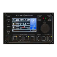
Primary operator interface and control unit containing display and control electronics.
Central distribution point for system components, housing control intelligence and voltage regulation.
Provides electronic heading reference by interacting with magnetic flux from a steering compass.
Facilitates electrical connection between the Distribution Unit and the Heading Sensor Coil.
Signals precise angular position and velocity of the rudder to the control unit.
Details for installing the control unit, including RFI considerations and mounting.
Guidelines for installing the distribution unit, noting its enclosure requirement.
Mounting instructions for the heading sensor coil relative to the magnetic compass.
Location and mounting advice for the junction box near the magnetic compass.
Instructions for mechanically coupling the rudder reference unit arm to the rudder arm.
Overview of cables for interconnecting units and GPS input for waypoint steering.
Details on connecting the control and distribution units, including power supplies.
Wiring diagrams for connecting the heading sensor coil via the compass junction box.
Connection procedures for the rudder reference unit, considering two conditions.
How to connect solenoids and details on common polarity configurations.
Connecting GPS/plotter for track steering data using NMEA 0183 sentences.
How the autopilot outputs heading and rate of turn data conforming to NMEA 0183.
Connecting external heading sources like electronic compasses or GPS gyros.
Connecting the autopilot to a CANbus interface for N2K communication.
Connecting to support watch alarm units for remote acknowledgement.
Guidance on routing cables to minimize radio frequency interference (RFI).
Procedure to set unique addresses for control units in multi-head systems.
Adjusting mechanical and electronic limit switches for rudder protection.
Connecting power supplies and ensuring correct isolator status before operation.
Checking rudder indicator response for correct phase connection.
Overview of the interactive menu for accessing and adjusting autopilot parameters.
Step-by-step guide to accessing the setup menu for parameter configuration.
Changing display mode between light characters on dark background and vice versa.
Adjusting rudder angle response to course error for optimal steering.
Setting the characteristic time for the automatic permanent helm integrator.
Configuring the function that cancels rudder offset on course changes.
Selecting operational modes (STD, NULL, OFF) for the autotrim function.
Calibrating the autopilot to recognize the mechanical midships position of the rudder.
Calibrating the rudder angle indicator to specific degrees for accurate feedback.
Setting the maximum rudder angle for activating all bars in the rudder angle display.
Enabling or disabling electronic limit switches as a backup or alternative.
Adjusting the port limit switch to operate at a required rudder angle.
Adjusting the starboard limit switch to operate at a required rudder angle.
Setting the rudder positioning sensitivity based on steering system integrity.
Automatic calibration of rudder movements to ensure stable, critically damped steering.
Selecting the appropriate sensor coil type (HSC1 or HSC2) for heading reference.
Setting the magnetic heading value based on the heading sensor coil.
Information on the magnitude of the heading signal from the sensor coil.
Specifying the priority source for heading data (Coil, NMEA, or N2K).
Selecting priority input between two NMEA heading data ports.
Prioritizing heading data type acceptance as MAG or TRUE.
Programming the time delay for the off-course alarm to avoid nuisance alarms.
Setting the baud rate for NMEA channel 1 heading data.
Adjusting NMEA heading output data update rate for compatibility.
Independently selecting the baud rate for NMEA channel 2 input.
Selecting track data input type between NMEA 0183 and N2K.
Setting the baud rate for NMEA 0183 track input data.
Setting the heading change angle for compensating set and drift in XTE mode.
Configuring an audible alarm for course changes within a specified range.
Programming audible alarms for custom turns.
Setting the alarm angle for automatic heading changes in track mode.
Programming the duration of audible and visual alarms for new course orders.
Setting the alarm reinstatement time after a course deviation.
Configuring notifications for remote steer station alarm status.
Adjusting magnetic deviation correction using manual or automatic methods.
Assigning unique addresses to control units for system identification.
Procedure to reset all installation programmed data to factory default levels.
Specifying the priority source address for heading data on the N2K bus.
Specifying the priority source address for track data on the N2K bus.
Assigning a node address for the autopilot transmitting data on the N2K bus.
Specifying the priority source address for GPS data on the N2K bus.
Enabling or disabling audible alarms for waypoint arrival in COG mode.
Selecting between single or dual power supplies to avoid power fail alarms.
Procedure to exit the setup menu and return to normal display operation.
Explanation of output stages for solenoid power supply and connection configurations.
Compatibility of the autopilot with various potentiometer types and calibration.
Information on auxiliary relay contacts and their response to autopilot operating modes.
Details on connecting and operating remote follow-up and non-follow-up steer stations.
Installation and function of the NT920WA watch alarm unit.
Operating instructions for the NT920NFU for temporary and permanent heading changes.
Operating instructions for the NT920FU for permanent heading changes via power steer.
Features and operation of the NT990FU remote proportional follow-up power steer control.
Operating instructions for the NT921HRC handheld follow-up power steer control.
Installation and calibration of the NT920RAI rudder angle indicator heads.
Functionality, compatibility, and operation of the NT920DHR/2 digital heading repeater.
Operation of the NT920AHR MK2 analogue heading repeater for displaying heading data.
Use of the relay box for switching higher voltage solenoids and providing isolated switching.
Connections and installation for NT990 BNWAS RST units for remote watch alarm acknowledgement.
How to switch the autopilot between OFF, STANDBY, and ON modes.
Engaging the autopilot from standby, confirming operational status.
Adjusting rudder application proportion to course error for optimal steering.
Defining autopilot sensitivity to course error and tolerance for short-term yaw.
Adjusting opposite rudder to prevent overshoot or arrest turns.
Adjusting panel illumination for day/night visibility and control values.
Accessing and adjusting parameters like rudder limit, OCA, and custom turns.
Using the reset key for alarm management and accessing working limits adjustments.
Engaging the track steering function using data from GPS/Track Plotter.
Enabling or disabling remote control units and power steer stations.
Applying and managing permanent helm offset to compensate for long-term heading errors.
Selecting and executing custom turns using dedicated keypad functions.
Rotating the course selector knob to order new heading changes efficiently.
Using cancel and confirm keys as backups for course changes and setup menu access.
Understanding the different display formats for setup, limits, and operating modes.
Procedures for conducting sea trials after completing setup and installation.
Checking if actual heading and set course values track ship's head movement accurately.
Step-by-step guide to engaging the autopilot for steering the vessel ahead.
Assessing and adjusting rudder application for course keeping and avoiding under/oversteer.
Adjusting rudder control for positive yaw correction without oversteer.
Calibrating loop gain to set the range of rudder angle per degree of course error.
Understanding autotrim compensation for long-term heading errors and manual cancellation.
How the autopilot automatically cancels rudder offset on course changes over a set angle.
Adjusting the time constant for autotrim to optimize performance in different conditions.
Adjusting counter rudder to prevent overshoot or arrest turns for efficient course changes.
Setting yaw control sensitivity to minimize unnecessary rudder movements in response to sea state.
Using the course selector knob to order small and large heading changes.
Selecting and executing course changes in 1°, 5°, or 10° steps using dedicated keys.
Performing temporary course changes using the dodge function and its keys.
Executing custom turns with programmable angles via keypad operations.
Using cancel and confirm keys as backups for course changes and setup menu access.
Acknowledging alarms, muting audibles, and accessing working limits.
Enabling or disabling remote stations and power steer controls via the remote key.
Controlling vessel track using GPS/Track Plotter data in XTE, BER, COG, or HTS modes.
Information on factory default settings and procedures for resetting them.
Correcting magnetic deviation electronically using automatic or manual procedures.
Adjusting parameters like rudder limit, OCA, and custom turns not accessible on control panel.
Information displayed during the initial power-up self-test sequence.
Identifying and understanding potential failure messages like communication or data errors.
Explaining display categories for non-track, track, and remote standby modes.
List of warning messages, their icons, and how alarms are acknowledged or silenced.
Understanding the meaning of status LEDs for autopilot modes and functions.
Accessing and interpreting diagnostic screens for tracing fault conditions.
Recommended initial settings for controls before engaging the autopilot.
Step-by-step guide to switching the autopilot on, starting with standby mode.
How to engage the autopilot and the confirmation indicators.
Adjusting rudder control to correct oversteer or understeer characteristics.
Ensuring actual heading matches the set heading using the autotrim function.
Using counter control to prevent overshoot or undershoot during course changes.
Reducing rudder movements caused by yawing by adjusting yaw control sensitivity.
How to change the vessel's heading using the course selector knob.
Executing course changes in 1°, 5°, or 10° steps using dedicated keys.
Performing temporary course changes using the dodge function and its keys.
Executing custom turns with programmable angles via keypad operations.
Controlling vessel track using GPS/Track Plotter data in XTE, BER, COG, or HTS modes.
Using cancel and confirm keys for course changes, track functions, and setup menu access.
Enabling or disabling remote stations and power steer controls via the remote key.
Using the reset key for alarm management and accessing working limits adjustments.
Operating the NT920NFU for dodge and power steer functions.
Engaging and disengaging the NT990FU follow-up power steer control.
Operating the NT921HRC handheld remote steer control for power steering.
| Type | Autopilot System |
|---|---|
| Manufacturer | Navitron |
| Model | NT777 MK2 |
| Course Setting Accuracy | ±1° |
| Heading Resolution | 1° |
| Interface | NMEA 0183 |
| Operating Temperature | -15°C to +55°C |
| Rudder Angle Limit | ±45° |