Do you have a question about the Navitron NT888G MK2 and is the answer not in the manual?
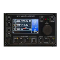
Overview of control unit display and initial settings for operation.
Instructions for switching the autopilot system between standby and off modes.
Steps to engage the autopilot system and its control modes.
Guide to manually adjusting steering parameters like Rudder, Yaw, and Counter.
How the Autotrim function aligns steered heading with the set heading.
Methods to reduce frequent rudder movements caused by yawing.
Procedures for changing the vessel's course using the autopilot.
Setting the maximum permissible rudder angle for safe turns.
Configuring automatic rate of turn during course changes.
Setting automatic radius of turn for course changes, requiring SOG data.
Fine-tuning Counter Rudder settings to prevent over/undershooting the target heading.
Engaging and operating the track steering facility with external route data.
How to cancel or acknowledge audible alarms using the TEST key.
Procedure to test the autopilot's alarm system functionality.
Using keypad functions for U-Turn, Next Course, and step course changes.
Accessing and adjusting system parameters via the Controls Menu.
Accessing and adjusting system limits such as Rudder Limit and alarms.
Enabling or disabling remote control stations and power steer inputs.
Adjusting display and keypad illumination levels.
Keys used for confirming or cancelling course changes and menu operations.
Operating the NT920NFU Dodge and Power Steer functions.
Operating the NT990FU Follow Up Power Steer functions.
Using third-party power steer and override controls with the autopilot.
Details on Autopilot modes, menus, keys, and operational displays.
Procedures for sea trials, type selection, and performance calibration.
Configuration of rudder, turn rate, radius, alarms, track, and deviation settings.
Information on second station units and power steer control options.
Information shown on the control unit during the power-up self-test sequence.
Displays indicating communication or interface errors during power-up.
Explanation of various messages displayed during normal autopilot operation.
Lists and types of alerts (warnings, alarms, cautions) generated by the system.
Accessing the diagnostic mode to trace fault conditions and engineering alarms.
Meaning of the indicator LEDs on the autopilot control unit panel.
| Brand | Navitron |
|---|---|
| Model | NT888G MK2 |
| Category | Autopilot System |
| Language | English |