Do you have a question about the NAVTELECOM SMART S-2423 and is the answer not in the manual?
Defines the primary functions and applications of the GPS-GSM Based Vehicle Tracking System.
Outlines the key operational tasks performed by the system, such as telemetering and data recording.
Explains the fundamental operational logic and data transmission flow of the device.
Details the technical specifications of the device, including GSM, GNSS, power, and interfaces.
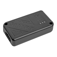
Describes the physical layout and components of the device unit, including connectors and indicators.
Lists the components included in the standard delivery package of the device.
Identifies and illustrates the individual physical components and parts of the device.
Details the pinout and function of the device's 14-pin interface connector and its various interfaces.
Details the physical installation process, including placement and orientation for optimal performance.
Explains how to install and configure the SIM card for device operation.
Describes how to connect the device to the vehicle's power supply and its internal battery.
Covers the connection and configuration of universal inputs for various sensor types.
Details how to connect and measure voltage from analog sensors to the device.
Explains how to connect and configure discrete sensors with two steady states (on/off).
Guides on connecting sensors that generate pulse or frequency signals for data acquisition.
Describes the functionality and usage of the device's internal accelerometer for various features.
Explains how to connect and control external low-current loads using the device's outputs.
Details how to connect digital sensors and identification keys using the 1-Wire interface.
Guides on connecting devices like fuel level sensors via the RS-485 digital interface.
Explains the different states indicated by the SYS system LED on the device.
Explains the different states indicated by the GSM modem LED on the device.
Explains the different states indicated by the NAV GPS/GLONASS LED on the device.
| Brand | NAVTELECOM |
|---|---|
| Model | SMART S-2423 |
| Category | GPS |
| Language | English |