Do you have a question about the nCase M1 and is the answer not in the manual?
Attaching the primary frame sections using M3-FS-5 screws.
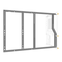
Continuing frame assembly with M3-FS-5 screws.
Instructions for removing and installing frame components with M3-FS-5 screws.
Assembling the bottom structural elements of the chassis using M3-FS-5 screws.
Attaching frame support pieces using M3-CS-8, M3-S-6, and M3-FS-5 screws.
Installing the initial bracket onto the chassis using M3-FS-5 screws.
Installing a second bracket using M3-FS-5 screws.
Demonstrates removing and reinstalling a bracket with M3-FS-5 screws.
Shows removing and installing a bracket for optimal placement with M3-FS-5 screws.
Installing a support bracket using M3-FS-5 screws.
Assembling the GPU support rails using multiple M3-FS-5 screws.
Attaching the bottom rails of the GPU support structure with M3-FS-5 screws.
Attaching the top rails of the GPU support structure with M3-FS-5 screws.
Instructions for installing a side panel at a specific angle.
Instructions for removing a side panel at a specific angle.
Manual guidance for attaching the top panel of the chassis.
Final step securing the assembly using M3-TB-10 thumb screws.
This document is an assembly manual for the NCASE M1 Vertical GPU Configuration, providing detailed instructions for setting up a computer case to support a vertically mounted graphics processing unit (GPU). The manual is designed as a "Flatpack Assembly Manual," indicating that the components are shipped disassembled and require user assembly.
The NCASE M1 Vertical GPU Configuration is an accessory or modification kit for the NCASE M1 computer case, designed to allow users to mount their graphics card vertically within the case. This vertical mounting orientation is primarily for aesthetic purposes, showcasing the GPU's design, particularly its cooler and RGB lighting, through a side panel window. Beyond aesthetics, vertical GPU mounting can sometimes offer improved airflow for certain GPU cooler designs, depending on the case's internal layout and fan configuration. The kit provides the necessary hardware and structural components to securely hold the GPU in this non-standard orientation, integrating it seamlessly into the existing NCASE M1 chassis. The assembly process involves several steps, including the removal of existing components, installation of new structural elements, and the secure fastening of the GPU bracket.
The assembly manual outlines a step-by-step process for configuring the NCASE M1 case for vertical GPU mounting. Key usage features highlighted by the manual's illustrations and instructions include:
Component Identification: The manual begins by identifying the various screws and standoffs required for assembly:
Modular Assembly: The NCASE M1 case itself is designed with a modular approach, and this vertical GPU kit follows suit. The assembly involves adding specific brackets and supports to the existing frame.
Initial Frame Assembly (Pages 2-4):
Base and Support Installation (Pages 4-7):
Riser Cable Integration (Pages 6-8):
Case Panel Installation (Pages 8-9):
Final Securing (Page 10):
While the manual primarily focuses on assembly, several aspects imply ease of maintenance:
Thumb Screws (M3-TB-10): The use of thumb screws for securing the top panel (and potentially other components, though only shown for the top panel) is a significant maintenance feature. Thumb screws allow for tool-less removal and reinstallation of panels, making it easy to access internal components for cleaning, upgrades, or troubleshooting without needing a screwdriver.
Modular Design: The modular nature of the NCASE M1 and its vertical GPU kit means that individual components can be removed or replaced if damaged or if the user wishes to revert to a standard horizontal GPU configuration. The explicit "Remove" instructions for certain components at the beginning of the assembly process suggest that these parts can be reinstalled if the vertical GPU setup is no longer desired.
Clear Disassembly Instructions (Implied): Although the manual is for assembly, the detailed steps and illustrations for installing components implicitly provide guidance for disassembly. For instance, if a component was installed with "X4 M3-FS-5," it can be removed by unscrewing those four screws. The "Remove" instructions for panels also directly address maintenance access.
Accessibility for Cleaning: The ability to easily remove side and top panels facilitates regular cleaning of dust filters and internal components, which is crucial for maintaining optimal performance and longevity of the computer hardware. The vertical GPU orientation itself can sometimes make GPU fans more accessible for cleaning, depending on the case design.
In summary, the NCASE M1 Vertical GPU Configuration manual provides a comprehensive guide for transforming the NCASE M1 case to accommodate a vertically mounted GPU. It emphasizes clear, step-by-step instructions with visual aids, utilizes a modular design for ease of assembly, and incorporates features like thumb screws that contribute to user-friendly maintenance and accessibility.
| Form Factor | Mini-ITX |
|---|---|
| Material | Aluminum |
| Motherboard Support | Mini-ITX |
| CPU Cooler Max Height | 130 mm |
| PSU Support | SFX, SFX-L |
| Expansion Slots | 2 |
| Weight | 3.2 kg |
| Volume | 12.6 liters |
| Maximum GPU Width | 140 mm |
| GPU Max Length | 317 mm |
| Maximum PSU Length | 130mm (SFX-L) |
| Dimensions | 328mm x 160mm x 240mm (L x W x H) |
| Cooling Support | 2 x 120mm (Side), 2 x 120mm (Bottom), 1 x 92mm (Rear) |