Do you have a question about the NDC BETA LaserMike LaserSpeed Pro 8500-4 and is the answer not in the manual?
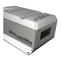
Details the manual's scope and the LaserSpeed 8500-4 gauge's function and technology.
Explains the core technology and measurement process of the LaserSpeed gauge.
Provides essential guidance on properly positioning the gauge for accurate measurements.
Details crucial safety precautions to follow during gauge installation and operation.
Explains the critical steps for aligning the gauge to ensure optimal measurement accuracy.
Provides instructions for correctly connecting the power supply to the gauge.
Details how to connect the gauge's output signals to external devices.
Provides the pinout details for the primary 25-pin connector.
Overview of all available interface connectors on the rear panel of the LS8500-4.
Detailed pinout information for the 25-pin D-Sub connector.
Detailed pinout information for the 9-pin D-Sub connector.
Details the pinout for the M12 Ethernet connector.
Provides comprehensive instructions for installing the LaserTrak software.
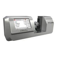
Details the various configuration screens within the LaserTrak software.
Configuration screen for common operating parameters.
Configuration screen for communication settings (RS232, RS422, SSI, Ethernet).
Explains baud rate and framing settings for serial communication.
Detailed descriptions of all available serial commands for configuration and data retrieval.
Guides on setting up the gauge's IP address for network connectivity.
Instructions for manually configuring the IP address via LaserTrak or HyperTerminal.
Details on using the UDP protocol for high-speed data transfer.
Information on obtaining and using the EtherNet/IP™ EDS configuration file.
Details the CIP assembly object for measurement data and configuration.
Explains access to LaserSpeed setup and measurement data via CIP database object.
Information on obtaining and using the PROFINET IO GSDML configuration file.
Details the data format for PROFINET IO input and output modules.
Explains the structure and use of the PROFINET IO PKW header for communication.
Information on obtaining and using the Profibus GSD configuration file.
Details the data format for Profibus input and output.
Explains the structure and use of the Profibus PKW header for communication.
Provides key technical specifications for all LaserSpeed gauges.
Details the specific technical specifications for the LS8500-4 model.
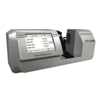
Highlights the main features and capabilities of the LS8500-4 gauge.
Describes the function and color of the LED indicators on the LaserSpeed Pro.
Details the air and liquid cooling requirements for the LS8500-4.
Provides physical dimension drawings for the LS8500-4 gauge.
Specific dimensional drawings for short-standoff gauge models.
Guidance on using a two-conductor supply for power connection.
Guidance on using a four-conductor supply for power connection.
Guides for resolving issues with serial and network communication.
Troubleshooting common problems related to quality factor and valid measurements.
Troubleshooting steps for Ethernet connectivity issues.
| Brand | NDC |
|---|---|
| Model | BETA LaserMike LaserSpeed Pro 8500-4 |
| Category | Measuring Instruments |
| Language | English |