Do you have a question about the Neles Metso T2 Series and is the answer not in the manual?
Provides essential information on T2 series ball valves and refers to separate actuator manuals.
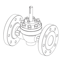
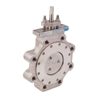
Describes the T2 series ball valve's construction: flanges/welding ends, top entry, one-piece body/ball/stem.
Details body markings and identification plate information, listing 10 marking types.
Lists key specifications like face-to-face length, body rating, pressure differential, flow direction, and leakage rates.
Mentions tightness and EN/DIN 50049 3.1 B certificates available on request.
States the valve meets European Directive 97/23/EC for pressure equipment and is marked accordingly.
Discusses valve part recyclability, material marking, and disposal instructions.
Provides critical safety warnings regarding temperature, weight, handling, and noise emission.
Instructs to remove flow bore protectors and check the valve for cleanliness.
Details precautions for handling weight, flange gasket centering, and avoiding pipeline misalignment.
Covers welding methods for end valves, temperature considerations for seals, and covering with wet protection cloth.
Provides guidance on actuator installation, referring to Section 6 and separate manuals.
Advises checking valve operation after installation and ensuring seats are protected from pressure.
Emphasizes using original spare parts and outlines service measures for end users.
Details steps for replacing leaking gland packing, including removing actuator and gland.
Explains how to clean jammed valves by flushing or using specific instructions.
Provides safety precautions and steps for detaching a B series actuator.
Gives crucial safety warnings and steps for removing the valve from the pipeline.
Outlines steps for dismantling the valve, including removing the actuator, bonnet, and ball.
Instructions for checking components of a dismantled valve.
Describes how to check seat rings, support rings, and O-rings for damage or impurities (Seat T).
Describes checking Seat H for damage and lapping requirements.
Details cleaning, checking sealing/bearing surfaces, and lapping the ball.
Explains checking bearings for standard and hi-temp constructions.
Provides detailed steps for cleaning, lubricating, and reassembling valve components.
Advises using suitable mounting parts and couplings for actuator installation.
Details steps for installing the M-type manual gear operator, including adjustments.
Explains how to install B1C-series actuators, emphasizing correct alignment and avoiding force.
General guidance for installing B1J series spring-return actuators.
Details installation for B1J type spring-return actuators, for spring-to-close operation.
Details installation for B1JA type spring-return actuators, for spring-to-open operation.
Notes Metso's non-responsibility for non-Metso actuators and compatibility requirements.
| Type | Control Unit |
|---|---|
| Manufacturer | Neles Metso |
| Supply voltage | 24 VDC |
| Enclosure | IP66 |
| Communication protocol | HART |
| Operating temperature | -40°C to +85°C |
| Series | T2 Series |