EasyManua.ls Logo

Nelson 75 User Manual

Nelson 75
22 pages
To Next Page IconTo Next Page
Page #1 background imageLoading...
Page #1 background image
Nelson Irrigation Corp. 848 Airport Rd. Walla Walla, WA 99362-2271 USA Tel: 509.525.7660 Fax: 509.525.7907 E-mail: info@nelsonirrigation.com Web site: www.nelsonirrigation.com
3
= Indicates that the gun connection options are available on the gun lower unit (for more detail see corresponding footnote key below).
The dimensions of the connections and the hole threads are shown on the next page.
Ø = Indicates that the connection is not available on the gun
11
11
1
The ANSI flange sizes which are available are (
2”2”
2”2”
2” for model 75 & 100 guns); (
3”3”
3”3”
3” for model 150 guns) and (
4”4”
4”4”
4” for model 200 guns). The bolts which
are needed for connecting the ANSI flanged gun must have thread 1/2-13 UNC-2B. This thread is tapped into the holes which are used for
connection of the flange to the riser flange. To get the 4” ANSI flange on the F200, an adapter is required (part #10565). The (8) flange holes are
threaded 1/2-13 UNC-2B. The adapter (part #10565) is sold separately. Bolts for the (8) threaded holes are not shipped with the flange adapter.
22
22
2
The Nelson Flange is unique to NIC. The gun can connect to pipe thread by using an adapter (flange-to-thread adapter). These add-on adapters
are available for sizes (
2”2”
2”2”
2” FNPT part #6860, FBSP part #7050); (
2.5”2.5”
2.5”2.5”
2.5” FNPT part #7040, FBSP part #7051) All adapters are sold separately. The
Nelson flange can also mate to the 2” QC valve key. The bolts which are needed for connecting the Nelson flange must have thread 3.12-18
UNC-2B. This thread is tapped into the holes. Bolts used for the threaded flange holes (6) are included and shipped with the gun.
33
33
3
The bolts and nuts are included and shipped with the gun for connecting through the flange holes (6 bolts and nuts).
44
44
4
The bolts (no nuts required) are included and shipped with the gun for the metric threaded flange holes (6 bolts).
55
55
5
Thread connection for these guns are comprised of the Nelson flange gun plus an add-on adapter (flange-to-thread adapter). Add-on
adapters are available in sizes (
3”3”
3”3”
3” FNPT part #8403-001, FBSP part #8820); (
3.5”3.5”
3.5”3.5”
3.5” FNPT part #6621, FBSP part #6621-001) and (
4”4”
4”4”
4” FNPT
part #9127). All these ‘flange-to-thread adapters’ are sold separately.
GUN CONNECTION OPTIONS
2/05
(SEE FOOTNOTE NUMBER FOR INFORMATION ON THESE GUN CONNECTIONS)
100
150
200
F100
F150
F200
SR100
SRA150
SR200
SR150
SRNV100
GUN MODEL
SR75
75
2
2

ØØØ
43
0
gun
only
3
4
4
3
Ø
Ø
Ø
5
5
2
5
3
4
sizes
1.5” 2”
size
2” 2.5”
size
2” 2.5”
size
2”
size
2”
size
2”
size
2”
sizes
1.5” 2”
5
5
5
5
4
ANSI
FLANGE
F75
sizes
1.5” 2”
2
sizes
1.5” 2”
1
NELSON
FLANGE
METRIC
FLANGE
FBSP
THREAD
FNPT
THREAD
Question and Answer IconNeed help?

Do you have a question about the Nelson 75 and is the answer not in the manual?

Nelson 75 Specifications

General IconGeneral
BrandNelson
Model75
CategoryLawn and Garden Equipment
LanguageEnglish

Summary

75 SERIES BIG GUN SPECIFICATION

GENERAL

Overview of 75 Series Big Gun sprinklers, pressure, and nozzle ranges.

DESIGN

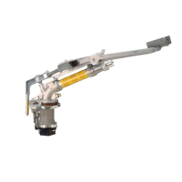
Details on the construction and components of the 75 Series Big Gun.

100 SERIES BIG GUN SPECIFICATION

GENERAL

Overview of 100 Series Big Gun sprinklers, pressure, and nozzle ranges.

DESIGN

Details on the construction and components of the 100 Series Big Gun.

150 SERIES BIG GUN SPECIFICATIONS

GENERAL

Overview of 150 Series Big Gun sprinklers, pressure, and nozzle ranges.

DESIGN

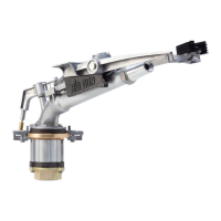
Details on the construction and components of the 150 Series Big Gun.

200 SERIES BIG GUN SPECIFICATIONS

GENERAL

Overview of 200 Series Big Gun sprinklers, pressure, and nozzle ranges.

DESIGN

Details on the construction and components of the 200 Series Big Gun.

SR75 BIG GUN DIMENSIONS

OVERALL DIMENSIONS

Detailed measurements and specifications for the SR75 Big Gun.

SR150 DIMENSIONS

OVERALL DIMENSIONS

Detailed measurements and specifications for the SR150 Big Gun.

SR200 DIMENSIONS

OVERALL DIMENSIONS

Detailed measurements and specifications for the SR200 Big Gun.

BIG GUN MATERIALS SPECIFICATIONS

GENERAL

General specifications for materials for contractor supply.

MATERIALS AND CONSTRUCTION

Details on materials used for body, drive arm, bearing, and braking system.

INSTALLATION

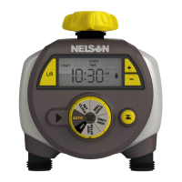
Contractor instructions for installation and adjustment of equipment.

MANUFACTURER

Identifies the required manufacturer and model number.

THRUST FORCE OF NELSON BIG GUN NOZZLES

H - HORIZONTAL THRUST FORCE OF 150 BIG GUN NOZZLES

Horizontal thrust force data for 150 Big Guns at 24° trajectory.

T — THRUST FORCE OF 200 BIG GUN NOZZLES

Total thrust force data for 200 Big Guns at 24° trajectory.

H - HORIZONTAL THRUST FORCE OF 200 BIG GUN NOZZLES

Horizontal thrust force data for 200 Big Guns at 24° trajectory.

RISER CONFIGURATION AND STABILITY

GUN AND VALVE COMBINATIONS

COUNTER BALANCE FOR OPERATION ON TILTED RISERS

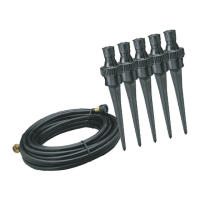
Kit to improve rotation on tilted risers for 100 & 150 Series.

OPTIONAL QUICK COUPLING VALVE AND KEY

Key for easy portability, connects to 2" or 3" QC valve.

NELSON QUICK COUPLING VALVE SPECIFICATION

Details of the 2" QC valve for SR75 and SR100 sprinkler guns.

NELSON SR75 GUN/800P VALVE COMBINATION

Specifications and diagram for SR75 gun with 800P valve combination.

SR100 43° WITH 800 SERIES VALVE

Diagram and configuration for SR100 43° gun with 800 Series valve.

SR150 43° + 800 SERIES 3" VALVE DIMENSIONS (METRIC)

Metric dimensions for SR150 43° gun with 800 Series 3" valve.

SR150 43° DIMENSIONS

Diagram of SR150 43° gun with 800 Series 3" valve and its dimensions.

Related product manuals