Shenzhen Neoway Technology Co., Ltd. Page 12 of 32
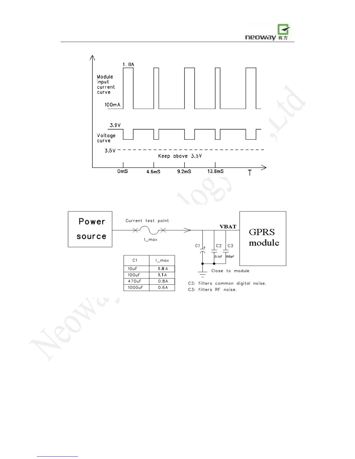
Figure 4 Burst Caused Current Peaks and Voltage Drops
Figure 5 Test Circuit and Peak Current
Results may vary depending on the ESR of capacitors, and the impedance of power source.
A low ESR 1000uF aluminum capacitor for C1 can be selected. As an alternative, a 470uF
tantalum capacitor is also suited. In case of Li-Ion cell battery used, 220uF or even 100uF
tantalum capacitor may be applicable because of the battery’s low internal impedance and the
ability to provide high transient current.
Use a low impedance power source, and keep the resistance of the power supply lines as low as
possible.