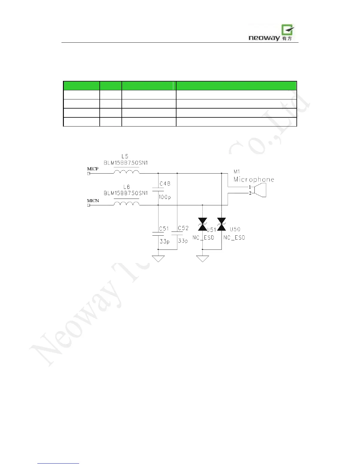
For reference audio interface see Figure 18. The peak-peak voltage routed to MIC+/MIC- should not
exceed 200mV. AGC circuit is integrated inside the module. Electret microphone is suited.
Figure 18 Reference design of microphone interface
A bias voltage for microphone is provided through MICP and MICN, as shown in Figure 19. But if
an amplifier is used between the microphone and module, capacitors like C1 and C2, should be
placed between the outputs of amplifier and module, to block the bias voltage.
For a peak-peak voltage greater than 200mV, an attenuation circuit comprised of R1-R4 should be
used.