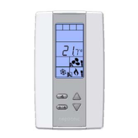
TRO5404
Specification & Installation instructions
2
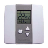
Mounting Instructions
CAUTION: Risk of malfunction. Remove power prior to separate thermostat cover from its base.
A. Remove the screw (captive) holding the base and the front cover of the thermostat.
B. Lift the front cover of the thermostat to separate it from the base.
C. Pull wire through the base hole.
D. Secure the base to the wall using wall anchors and screws (supplied). Make the appropriate connections.
E. Mount the control module on the base and secure using the screw.
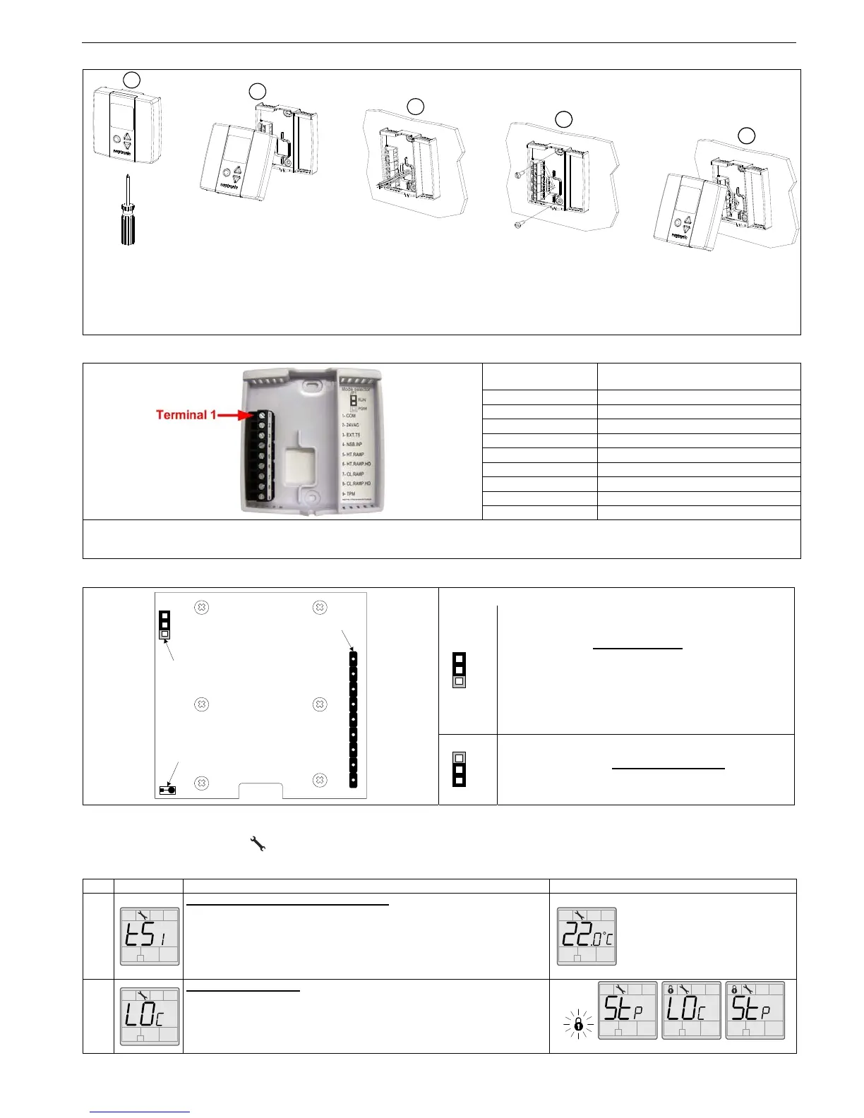
Terminal description
Terminals TRO5404
1 Common
2 24 VAC
3 Exterior temperature sensor
4 Night set back input*
5 Heating ramp
6 Heating ramp high demand
7 Cooling ramp
8 Cooling ramp high demand
9 TPM (time proportional modulation)
*For a replacement in an existing night set back (NSB) loop with thermostat PTA, the NSB input, terminal #4, of the TRO should be
isolated for a good performance.
Settings on PC Board
Mode Selection
Jumper (JP1) on RUN:
Thermostat is in operation mode
.
Thermostat must be set in this mode to operate
properly.
If not locked, set point and control mode (Heating &
Cooling ON, Cooling only ON or Heating only ON)
may be modified by end user.
Jumper (JP1) on PGM:
Thermostat is set in Programming mode
.
Refer to following section about all settings
description
Programming mode
When in this mode this symbol is displayed. Please press on button to advance to the next program function and press on or
to change value. You can leave the programming mode at any time, changed values will be recorded.
Step Display Description Values
1
Internal temperature sensor Calibration:
Display switches between “tS1” and temperature read by internal
temperature sensor.
You can adjust the calibration of the sensor by comparison with a known
thermometer. For example if thermostat has been installed in an area where
temperature is slightly different than the room typical temperature
(thermostat place right under the air diffuser).
Range : 10 to 35ºC [50 to 95ºF]
Increment:1ºC [1ºF]
NOTE: This thermostat has been
calibrated at factory
2A
Locking the set point :
Display switches between “LO
C” and “Stp”.
You can lock or unlock the set point adjustment by end user. If locked the
lock symbol will appear.
If you do not want to lock set point adjustment by end user, go directly to
step #3.
Default value: Unlocked
A
E
D
C
B
1 2 3 4 5 6 7 8 9
JP1
Mode selector
COM
PGM
TB1
connecting
strip
TPM
CL.RAMP.HD
CL.RAMP
HT.RAMP.HD
HT.RAMP
NSB.
INP
EXT.TS
24VAC
Temperature
sensor
RUN
PGM
RUN
PGM
RUN
 Loading...