Do you have a question about the Nescafe Dolce Gusto BEVERAGE CENTER GENIO 2 and is the answer not in the manual?
Details the external components of the beverage center with numbered labels and descriptions.
Illustrates and describes the internal components of the beverage center with numbered labels.
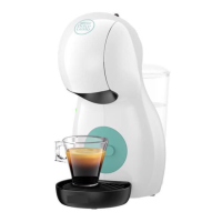
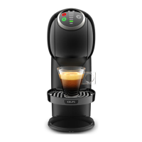
Explains the information and data codes found on the Krups machine's rating plate.
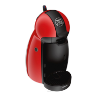
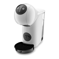
Details the information and data codes present on the De'Longhi machine's rating plate.
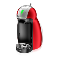
Provides an example of a Breville machine's rating plate and its associated information.
Illustrates the water flow path and components within the beverage center.
Lists key technical specifications including voltage, power, energy consumption, and capacities.
Provides various operational data and physical dimensions of the beverage center.
Details the vertical clearance measurements for different cup sizes under the coffee outlet.
Explains the meaning of LED signals on the power button and bargraph for various operating modes and errors.
Describes the three functions of the bargraph display: filling quantity, countdown timer, and flashlight signal.
Step-by-step guide for the initial rinsing and setup of the new beverage center.
Continues the step-by-step guide for the initial rinsing and setup of the new beverage center.
Detailed instructions on how to select and brew a beverage using a capsule.
Continues the instructions for brewing a beverage, including capsule removal and cleaning.
Explains the automatic power-saving feature and procedures for emptying the fluid system for shipping.
Continues the instructions for emptying the fluid system and notes on error mode indicators.
A checklist to help locate faults and initiate appropriate repair actions.
Guides on diagnosing issues when the machine is plugged in and switched on.
Addresses problems encountered during beverage preparation, such as temperature and extraction.
Covers issues related to leaks, incorrect flow rate, and loud noises or vibrations.
Provides essential safety information and general assembly notes before starting repairs.
Lists the necessary tools and accessories required for performing disassembly and repair work.
Step-by-step guide for removing, cleaning, and deblocking the needle plate assembly.
Details the assembly of the needle plate and the importance of thorough flushing after repairs.
Instructions for removing detachable parts and loosening screw connections for general disassembly.
Step-by-step instructions on how to unlatch and remove the right side panel of the machine.
Detailed steps for unlatching the right side panel, highlighting delicate latch positions.
Instructions for unlatching and removing the left side panel of the machine.
Procedure for replacing the water tank connector, including assembly tips.
Steps for removing and replacing the flowmeter, including connector and hose details.
Instructions for unplugging pump connectors and starting pump removal.
Continues pump removal, detailing hose disconnection and pump support removal.
Details alternative disassembly for pump support and continued pump removal steps.
Provides guidance on cutting pressure hoses and connecting them during pump assembly.
Step-by-step guide for removing and replacing the NTC temperature sensor.
Provides assembly guidance for the NTC sensor, including heat conducting paste and holding plate placement.
Instructions for replacing the power cord and integrated thermo fuses.
Details the process of loosening screws and removing cable lugs, fuse holder clips, and thermo fuses.
Offers assembly tips for the power cord, including receptacle connection and thermofuse spacing.
Instructions for disassembling and removing the thermoblock, including safety warnings.
Details pulling the thermoblock and holder from the main housing and assembly tips.
Guide on cutting and connecting pressure hoses for the thermoblock assembly.
Step-by-step guide for unplugging connectors and removing the electronic mainboard.
Provides guidance for handling and installing the new electronic mainboard, including ESD precautions.
Instructions for removing and replacing the locking handle and control unit assembly.
Details removing the control unit and starting the replacement of the electromagnet.
Provides assembly tips for the electromagnet, including glove usage and alignment.
Step-by-step guide for unplugging connectors and removing the extraction head.
Offers guidance for attaching the new extraction head, including cable routing and locking lever.
Shows the wiring connections for the HMI PCB, MCU, and other components.
Lists and illustrates the specialized equipment required for performing functional tests.
Procedure for measuring the machine's heating up time and the criteria for a successful test.
Details the test device assembly and setup for measuring flow rate and water temperature.
Guides on performing flow rate, temperature, and maximal pressure tests with specific criteria.
Covers legal obligations for repair centers and necessary test equipment standards.
Procedure for testing the protective earth conductor's resistance for safety.
Details testing the insulation resistance between conductors and touchable parts.
Measures leakage current in the protective earth conductor when the machine is switched on.
Tests the contact current of touchable metallic parts on the machine.
Instructions for preparing the machine and the descaling solution before starting the process.
Details the descaling process for the hot water circuit and machine status indicators.
Continues descaling with waiting times and hot water circuit rinsing.
Covers cold water circuit rinsing, final cleaning, and machine drying after descaling.
Guide on regular cleaning of removable parts and the machine exterior.
Continues daily care instructions, including cleaning the machine body and drip tray.
Steps for packing the beverage center and accessories securely for transportation.
Final steps for boxing the machine and securing the package for shipment.
Diagram showing external spare parts for Krups models with corresponding labels.
Diagram showing upper internal spare parts for Krups models with corresponding labels.
Diagram showing lower internal and electrical spare parts for Krups models with labels.
A table listing Krups spare parts with descriptions and part numbers.
Diagram showing external spare parts for De'Longhi models with corresponding labels.
Diagram showing upper internal spare parts for De'Longhi models with corresponding labels.
Diagram showing lower internal and electrical spare parts for De'Longhi models with labels.
A table listing De'Longhi spare parts (1-24) with descriptions and part numbers.
A table listing De'Longhi spare parts (25-26) with descriptions and part numbers.
| Brand | Nescafe Dolce Gusto |
|---|---|
| Model | BEVERAGE CENTER GENIO 2 |
| Category | Coffee Maker |
| Language | English |