InstallatIon & sEtUP
3
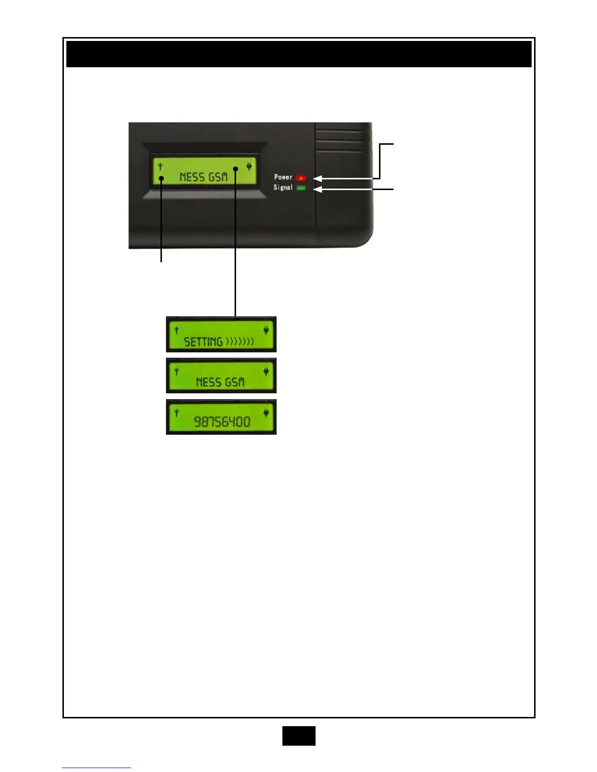
DISPLAY & LEDS
POWER LED
When on indicates
mains and battery are
connected
SIGNAL LED
OFF: No GSM network.
FLASHING: SIM card not
found.
ON: Connected to GSM
network.
SIGNAL
STRENGTH
INDICATOR
Normal standby condition.
The telephone number is
displayed as it is dialled by the
alarm panel.
Display during power up.
INSTALLATION CHECKLIST
1. Install the GSM unit in secure tamper-protected plastic housing. The Ness
101-008 housing is ideal.
2. Install the supplied NESS SIM card, (the SIM card may already be installed).
3. Connect a standard RJ45 telephone lead from the alarm panel’s dialler to the
TEL1 socket on the GSM unit.
4. Connect the antenna cable to the antenna socket and mount the antenna in a
position at least 1m away from the GSM unit.
5. Plug in the supplied 12VDC plug pack to the power socket.
6. Turn on the power switch.
7. Check the signal strength indicator on the LCD display and if necessary
reposition the antenna for best signal reception.
8. Program your alarm panel as required for monitoring back to base or to a
private phone. The GSM unit requires no programming.
9. Check operation by sending a test alarm.
 Loading...