Do you have a question about the Net Safety MILLENNIUM II and is the answer not in the manual?
Seller warrants product quality and performance against defects under normal use and care.
Limits seller's liability for damages, consequential damages, and punitive damages.
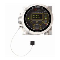
Overview of the Millennium II gas detection system composition and features.
Guide for users on transmitter and sensor configuration, operation, and maintenance.
Instructions for checking components after unpacking for damage or missing items.
Guidelines for securely mounting the transmitter and sensor, considering all requirements.
Details about the transmitter electronics module and its relay options.
Instructions for rotating the electronics module within the transmitter enclosure.
Guidelines and warnings for installing wiring in the field.
Recommendations for selecting and installing appropriate instrumentation cable to minimize interference.
How to configure analog output settings using jumpers for isolated or non-isolated supply.
Configuration of jumpers for remotely mounted sensors to establish communication.
Details on connecting sensor wires to transmitter terminals and power output terminals.
Wiring a remote reset for latched alarms using a push-button switch.
Guidelines for remote sensor mounting, including separation limits and junction box requirements.
General wiring diagrams for analog signal output configurations.
Pre-operation checks to ensure proper installation and safety of the transmitter and sensor.
Description of the transmitter's warm-up routine and initial display upon power application.
Information about the Organic LED (OLED) display and its features.
Explanation of the Status LED colors and patterns indicating transmitter/sensor states.
How to measure loop current using test jacks on the display module without opening the circuit.
Accessing the menu by opening the enclosure and using physical buttons.
Accessing the menu without opening the enclosure using a magnet and reed switches.
Overview of available functional settings and options accessible through the main menu.
Step-by-step guide on how to navigate through the transmitter's main menu options.
Detailed procedure for performing a full calibration of the sensor using span gas.
Procedure for performing a zero calibration using clean air or surrounding ambient air.
How to enable or disable transmitter channels for single or dual sensor models.
Procedure for viewing and setting low and high alarm levels for each channel.
Configuring alarm relay coils for energized/de-energized and latching/non-latching operation.
Assigning alarm relays to specific channels and alarm points.
Setting alarm modes for oxygen sensors, including Above-Above, Below-Below, and Below-Above.
Option to select the display language from English, Spanish, French, or Portuguese.
Configuration of MODBUS parameters like slave address, baud rate, and parity.
Setting the current date for event logging purposes.
Setting the current time for event logging purposes.
Accessing and viewing stored events, including event types and timestamps.
Performing a manual reset after calibration failure or to clear latched alarms.
Initiating a self-test for relays to ensure proper functioning.
Setting the upper detection limit or range for a specific sensor.
Selecting the target gas type or correction factor for sensors.
Selecting the calibration gas value for sensor calibration procedures.
Displaying the serial number and firmware version of the transmitter.
How the transmitter monitors itself for system faults and indicates them.
Description of standard and solid-state relays, their ratings, and configuration options.
Information about the 4-20mA current output for transmitting status and fault codes.
Table detailing sensor status, LED indicators, current output values, and their meanings.
Description of the RS-485 Modbus RTU protocol and configuration requirements.
Recommendation for performing bump tests every 90 days to ensure system accuracy and functionality.
Steps to take when problems arise, including checking wiring, voltage, and contacting service.
Guidelines for storing the transmitter and its components to protect them from environmental factors.
List of available spare parts and accessories with Net Safety part numbers.
Procedure for returning equipment for repair, including required information and shipping instructions.
| Output | 4-20 mA, HART |
|---|---|
| Type | Fixed Gas Transmitter |
| Detection Principle | Catalytic bead |
| Enclosure Rating | NEMA 4X, IP66 |
| Certifications | ATEX, IECEx, CSA |
| Target Gas | Oxygen |
| Power Supply | 24 VDC nominal |
| Operating Temperature | -40°C to +85°C |