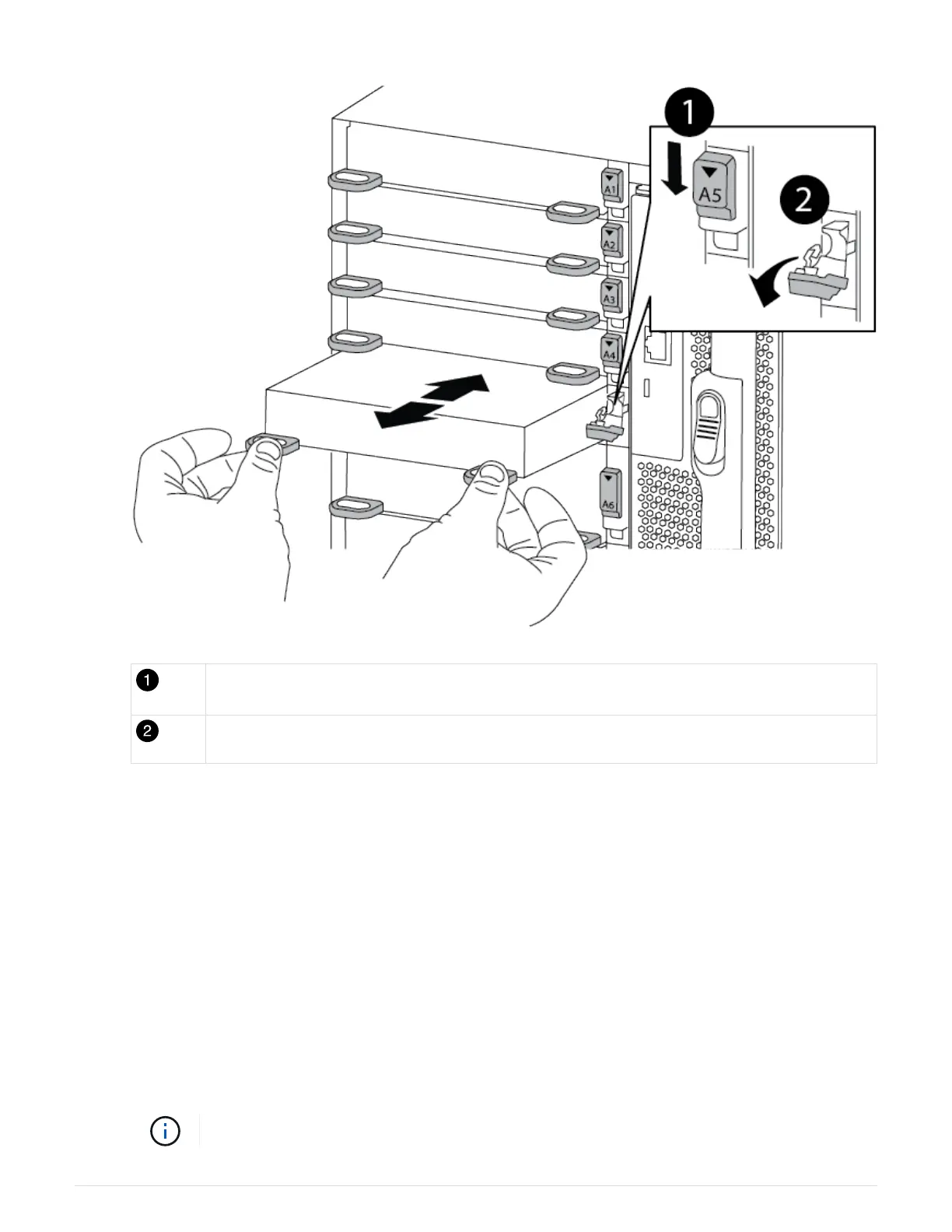
Lettered and numbered I/O cam latch
I/O cam latch completely unlocked
4. Install the I/O module into the target slot:
a. Align the I/O module with the edges of the slot.
b. Slide the I/O module into the slot until the lettered and numbered I/O cam latch begins to engage with
the I/O cam pin.
c. Push the I/O cam latch all the way up to lock the module in place.
5. Repeat the remove and install steps to replace additional modules for controller A.
6. If the replacement I/O module is a NIC, cable the module or modules to the data switches.
7. Reboot the controller from the LOADER prompt:
a.
Check the version of BMC on the controller:
system service-processor show
b.
Update the BMC firmware if needed:
system service-processor image update
c.
Reboot the node: bye
This reinitializes the PCIe cards and other components and reboots the node.
706
 Loading...