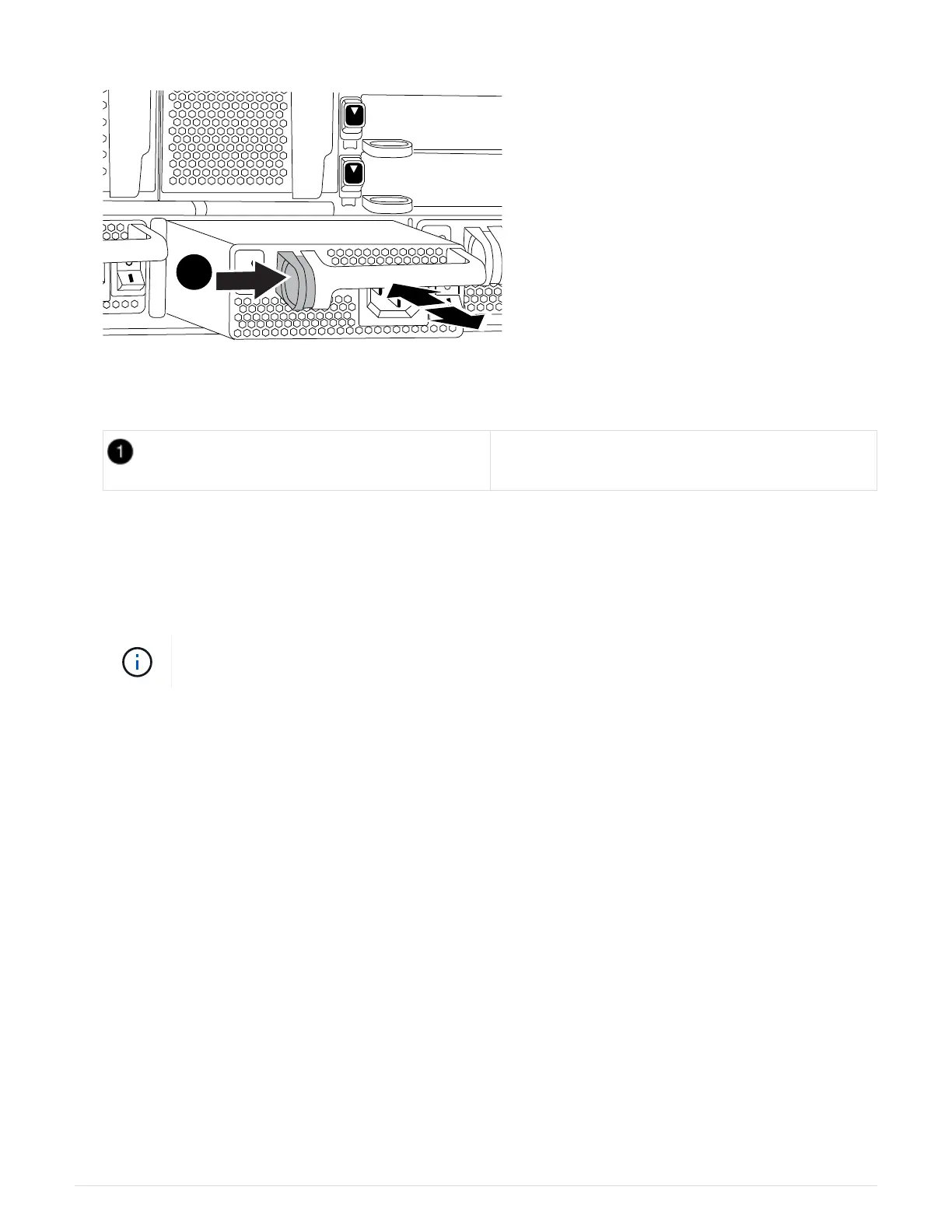
Locking button
5. Make sure that the on/off switch of the new power supply is in the Off position.
6. Using both hands, support and align the edges of the power supply with the opening in the system chassis,
and then gently push the power supply into the chassis until it locks into place.
The power supplies are keyed and can only be installed one way.
Do not use excessive force when sliding the power supply into the system. You can damage
the connector.
7. Reconnect the power supply cabling:
a. Reconnect the power cable to the power supply and the power source.
b. Secure the power cable to the power supply using the power cable retainer.
Once power is restored to the power supply, the status LED should be green.
8. Turn on the power to the new power supply, and then verify the operation of the power supply activity
LEDs.
The green power LED lights when the PSU is fully inserted into the chassis and the amber attention LED
flashes initially, but turns off after a few moments.
9. Return the failed part to NetApp, as described in the RMA instructions shipped with the kit. See the
Part
Return & Replacements
page for further information.
Replace the real-time clock battery
You replace the real-time clock (RTC) battery in the controller module so that your
system’s services and applications that depend on accurate time synchronization
continue to function.
559