Step Perform on each controller
Cable controller management (wrench) ports.
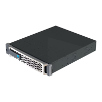
Cable 25 GbE network switches:
Ports in slot A3 and B3 (e3a and e3c)
and slot A9 and B9 (e9a and e9c) to the
25 GbE network switches.
40GbE host network switches:
Cable host‐side b ports in slot A4 and
B4 (e4b) and slot A8 and B8 (e8b) to
the host switch.
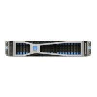
Cable 32 Gb FC connections:
Cable ports in slot A5 and B5 (5a,
5b, 5c, and 5d) and slot A7 and B7
(7a, 7b, 7c, and 7d) to the
32 Gb FC network switches.
•
Strap the cables to the cable
management arms (not shown).
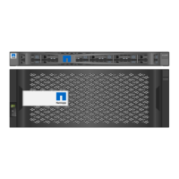
• Connect the power cables to the PSUs and
connect them to different power sources (not
shown).
PSU 1 and 3 provide power to all side A
components, while PSU2 and PSU4 provide
power to all side B components.
Option 2: Switched cluster
Management network, data network, and management ports on the controllers are connected to switches.
The cluster interconnect and HA ports are cabled on to the cluster/HA switch.
Before you begin
You must have contacted your network administrator for information about connecting the system to the
switches.
Be sure to check the direction of the cable pull-tabs when inserting the cables in the ports. Cable pull-tabs
are up for all networking module ports.
688