• Install rail kits, as needed, using the rail kit
installation instructions.
• Install the empty chassis into the system cabinet or rack.
• Reinstall the system components into the chassis,
matching the chassis slot ID with the slot ID
sticker on the component.
• Attach cable management arms.
• Place the bezel on the front of the system.
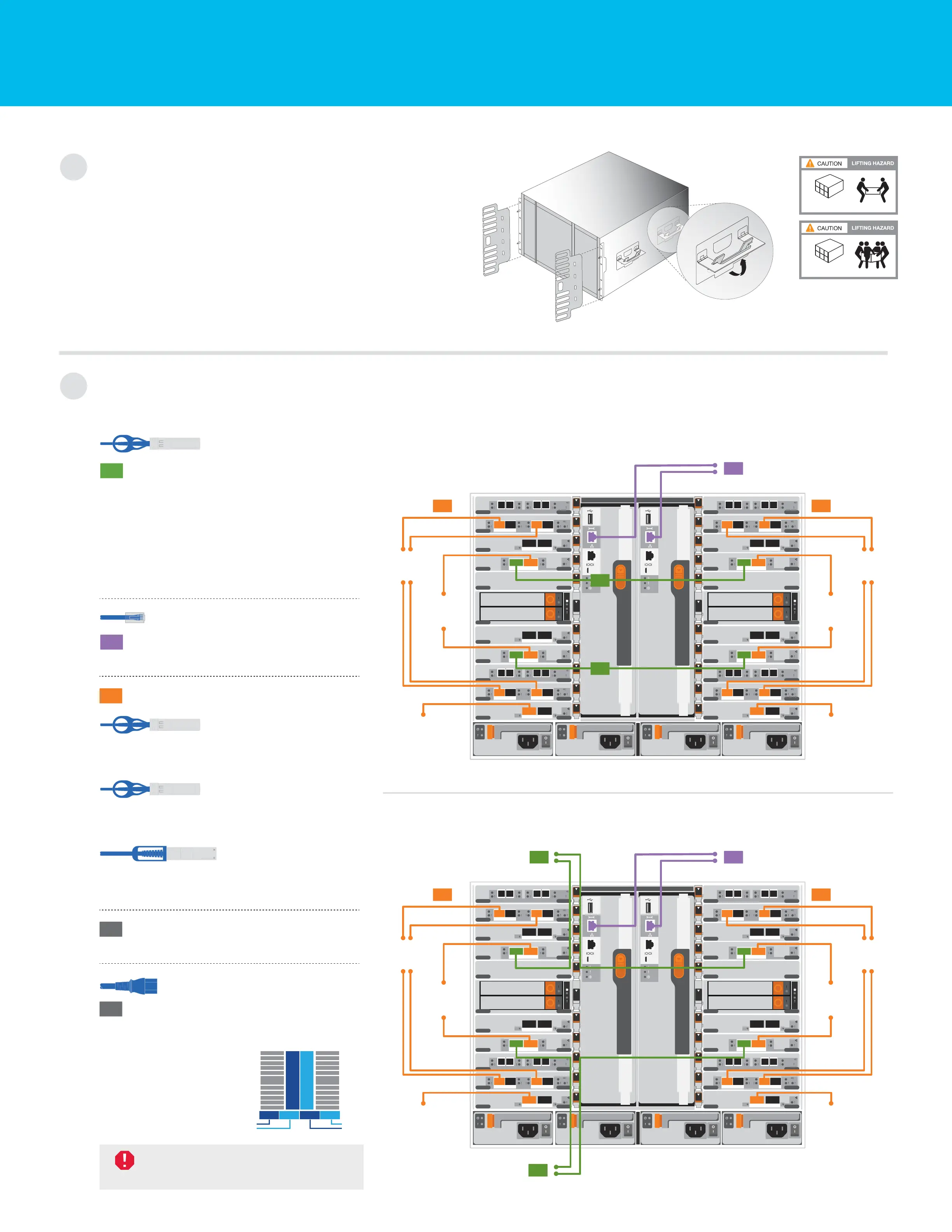
Install system in a rack or cabinet:
Cable controller for a switchless or switched cluster:
See your network administrator for help connecting to your switches.
DO NOT power on
controllers at this point.
Handles and cable
management arms
240 lbs. (109 kg)
Fully-populated chassis
90 lbs. (41 kg)
Empty chassis
2
1
Switchless cluster:
Cable cluster interconnect ports a
together in slot A4 and B4 (e4a) and
again in slot A8 and B8 (e8a).
Switched cluster:
Connect ports a in slot A4, B4, A8 and B8
(e4a, e8a) to the cluster switch. Use the
cables supported by your switch.
Connect the wrench ports
to the management switches.
On both controllers:
Connect e2a, e2c, e10a, and e10c
to the 10 GbE data or FC switches.
Connect e4b and e8b to the
40 GbE data switches.
Connect e11a to the 100 GbE
data switches.
Strap the cables to the cable
management arms (not shown).
Connect the power cables to the PSUs
and connect them to different power
sources (not shown).
4
5
1
2
3
Cluster interconnect cable
(PN 112-00542 or 112-00543)
10 GbE network cable
(
PN 112-00299, 112-00300 or 112-00301)
40 GbE network cable
(
PN 112-00543, or 112-00543)
Ethernet cable
Power cable
Switchless cluster
Switched cluster
PSU 1 and PSU 3
provide power to
all side A FRUs,
PSU 2 and PSU 4
provide power to
all side B FRUs.
A
PSU 1 PSU 2 PSU 3 PSU 4
B
2nd
power
source
1st
power
source
100 GbE QSFP28 copper cable
B5
B6
B4
B3
B2
B1
B10
B9
B8
B7
B11
A5
A6
A4
A3
A2
A1
A10
A9
A8
A7
A11
a b c d
a b c d
6-2
6-1
a b c d
a b c d
a b
a b
a b c d
a b c d
6-2
6-1
a b c d
a b c d
a b
a b
a b
a b
a b
a b
a b
a b
3
To 40 GbE
data network
switches
1
1
Controller A
PSU 1
Controller B
PSU 2 PSU 3 PSU 4
2
To management
network switches
To 100 GbE
data network
switches
To 10 GbE data
or FC network
switches
3
To 40 GbE
data network
switches
To 100 GbE
data network
switches
To 10 GbE data
or FC network
switches
B5
B6
B4
B3
B2
B1
B10
B9
B8
B7
B11
A5
A6
A4
A3
A2
A1
A10
A9
A8
A7
A11
a b c d
a b c d
6-2
6-1
a b c d
a b c d
a b
a b
a b c d
a b c d
6-2
6-1
a b c d
a b c d
a b
a b
a b
a b
a b
a b
a b
a b
3
To 40 GbE
data network
switches
Controller A
PSU 1
Controller B
PSU 2 PSU 3 PSU 4
2
To management
network switches
To 100 GbE
data network
switches
To 10 GbE data
or FC network
switches
3
To 40 GbE
data network
switches
To 100 GbE
data network
switches
To 10 GbE data
or FC network
switches
1
To cluster switches
1
To cluster switches
Install hardware | Stage 2
 Loading...