3
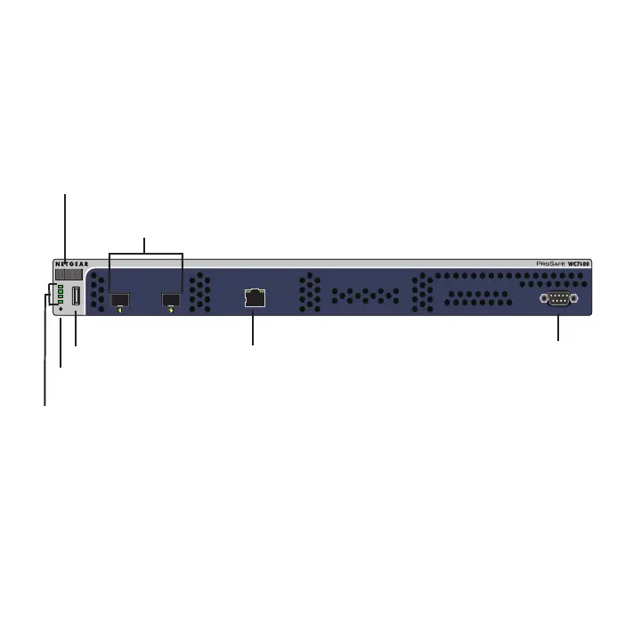
Meet Your Wireless Controller
Before you install your wireless controller, familiarize yourself with its
LEDs, buttons, and ports.
Front Panel
Console 9600,N,8,1
LED Mode:
Left LED: Green=Link at 1G E,
Yellow=Link at 10/100M
Right LED:Green=Link,
Green Blink=Active
LED Mode:
Green= Link at 10G, Blink Green=10G Active,
Yellow=Link at 1G, Blink Yellow=1G Active
Power
Status
Fan
Stack
Master
Reset
USB
ID
LEDs (top to bottom):
Power, Status, Fan, Stack Master
Reset button
USB port
Digital access point counter
Slots and LEDs for optional
Ethernet port and LEDs
SFP GBIC modules
COM port
 Loading...