Do you have a question about the New lift FST-2 and is the answer not in the manual?
Explains the scope and goals of the FST-2 manual for experienced lift experts.
Describes signs and symbols used in the manual, like key combinations and actions.
Lists other available documentation for the FST-2 Controller and its components.
Lists the standards and regulations the FST-2 Controller complies with, including German and European lift regulations.
Details the FST-2 Controller's compliance with EMC standards and its resistance to electrostatic discharges and transient disturbances.
Provides guidelines for handling electronic components, including keeping them in original packaging and grounding before touching.
Explains the LC-Display of the FST-2 Controller, its four lines (A, B, C, D), and displays in normal and diagnostic modes.
Describes the operation of the FST-2 Controller using seven keys and their functions in different displays.
Explains the function of the three LEDs on the FST-2 Controller front panel for displaying device status.
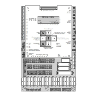
Provides an overview of the FST-2 Controller's components and bus plan, detailing installation sites and LON bus connections.
Lists the components and features of the FST-2 Controller, including its main circuit board, interfaces, memory, and I/O capabilities.
Explains how FST software parameters are set using the FST-2 user interface and the division of menu items into security levels.
Details menu items within the "Service" section, including error list, service counters, and statistics reset for maintenance.
Covers drive-related menu items such as start monitoring, drive type selection, brake monitoring, and relevelling parameters.
Explains configuration options including installation settings, priority landing, auto test drive, LON configuration, and modem/fax settings.
Details positioning parameters for linear and incremental positioning, including floor settings, zone switches, and relevelling limits.
Describes landing call programs, door programs, special call modes, and Lift-Boy mode for managing lift calls.
Covers system settings such as time/date, password settings, language, recorder functions, and PC-Card operations.
Details door operation settings, including number of doors, cam delay, lock delay, nudging, photocell, and door lock types.
Provides a general overview of the main menu and password protection for accessing different security levels.
Outlines various test functions available, such as fault reset, door tests, auto test drive, service mode, and end switch tests.
Describes the characteristics of programmable inputs/outputs, including assigned functions, signal direction, and active states.
Explains how input functions are triggered by changes in the input/output state from inactive to active.
Details how output functions are activated when their specified conditions are met, changing the input/output state.
Defines "Flag" as a special function linking controller states with an "OR" condition, allowing for debounced or delayed control.
Explains "Signals" as a function that links controller states using an "AND" condition, activating outputs when all required conditions are met.
Describes how programmable inputs can be used to block or enable car and landing calls for any floor, assigning call combinations.
Explains how arbitrary error and event messages can be output via programmable input/output, with settings for ID and Ctrl.
Details the process of programming inputs and outputs via the FST menu, specifically within the I/O Configuration submenu.
Explains the RAW register as an 8-digit hexadecimal value for assigning functions, setting active states, signal direction, and parameters.
Lists all functions that can be allocated to a RAW register, indicating whether they have parameters and providing page references.
Provides examples of RAW register values for functions without parameters, illustrating their hexadecimal representation.
Explains how the "landing call" function enables placing landing calls via programmable input/output, detailing RAW register assignments.
Describes the "fire signal" function for triggering fire evacuation drives via programmable input/output, including RAW register configurations.
Details the "priority landing" function for initiating priority landing drives via programmable input/output, showing RAW register assignments for different floors and doors.
Explains the "position indicator" function for outputting coded position signals to programmable input/output, showing RAW register examples for HEX and GRAY codes.
Describes the "flag" function for activating programmable input/outputs based on controller states linked by an "OR" condition, with debouncing/delay options.
Explains how to set flags in the FST menu, linking controller states via an "OR" condition using mask parameters.
Describes how the "user error" function outputs error messages from the error list to programmable input/output, with settings for ID and Ctrl.
Details the "signal" function for outputting an "AND" link of controller signals to programmable input/output, providing examples of RAW register configurations.
Explains the "evacuation" function for triggering evacuation drives via programmable input/output, detailing RAW register settings for evacuation speed and door states.
Describes the "special drive" function for triggering special drives using programmable input/output, including target floors and drive speeds.
Explains the "alarm misuse" function for controlling a relay to suppress unjustified emergency calls, detailing activation conditions and delay settings.
Details the "speed threshold" function for outputting if speed falls below a set threshold, including calculation of RAW register values.
Describes the "ramp drive" function for providing inputs for controlled car movements in an extended door zone, including required inputs and RAW register settings.
Explains the "override floor blocking" function for deactivating floor blocking via programmable input/output, detailing RAW register configurations for car and landing calls.
Details the "block floors" function for dynamic floor blocking using programmable input/output, showing RAW register configurations for different floor groups and call types.
Explains how the FST-2 Controller stores event and error messages and how they can be accessed via the LC-Display.
Describes the keypad functions used to navigate through the error list and access different information bytes or the initial display.
Lists event messages with their codes, descriptions, and reasons, covering topics like power supply, inspection, software updates, and orientation drives.
Details error messages with codes, descriptions, and reasons, including CPU errors, drive errors, door lock issues, and communication failures.
Covers the "DOOR OPEN FAILED" error, its description, reasons, and troubleshooting steps related to door drives, safety circuits, and FSM relays.
Details the "DOOR CLOSE FAILED" error, including reasons related to mechanical/electrical blocking and FSM relay checks.
Explains the "DOOR LOCK RETRY CNT" error related to failed shaft door lock attempts and the "Lock fail Max" parameter.
Describes the "DRM-START PROBLEM" error where the car does not start moving even with pre-selection active, suggesting encoder checks.
Covers the "DRM-DRIVE MONITOR" error indicating no car movement detected during a drive, possibly due to encoder issues or connection problems.
Details the "DRM-ENCODER FAILURE" error related to faulty car position plausibility testing with the encoder, suggesting encoder checks and commissioning verification.
Explains the "DRM-CAR COMMS FAIL" error indicating faulty communication between FST Controller and FSM car control module, pointing to cable and jumper issues.
Covers the "DRM-END FLOOR SPEED" error related to triggered delay control circuits at top/bottom limits, suggesting reset via TEST MENU.
Details the "DRM-MISSING ZONE" error where no zone message is received from the safety circuit despite reaching a levelling position, requiring safety circuit checks.
Explains the "DRM-BRAKE FAILURE" error where brakes do not react or release, indicating issues with pre-selection or monitoring inputs.
Covers the "DRM-MOTOR FAILURE" error related to drive temperature monitoring triggering, likely due to motor overheating.
Details the "DRM-FORCED STOP" error when a programmable input signal is active, shutting down the car with doors open.
Explains the "DRM-EMERG.LIMIT SW" error when the top emergency end switch is triggered, often related to terminal FST X14.6.
Covers the "DRM-DOOR FAILURE" error where the car door cannot be moved, indicating active door control but lack of door movement.
Details the "DRM-CONTACTOR MONIT." error when contactor drop-out protection is triggered, suggesting checks on terminal FST X1.23.
Explains the "DRM-SPECIAL I/O-PORT" error when a special function monitored by a programmable input fails, requiring checks on sequence.
Covers the "SLIP OUTSIDE LEVEL" error indicating unexpected car movement out of stopping position, possibly due to long deceleration or late brake activation.
Details the "SLIP OUTSIDE ZONE" error for unexpected car movement out of the zone, suggesting issues with deceleration distance or brake activation.
Explains the "DRIVE: CHKSUM-ERROR" for errors during drive data transmission, indicating an internal error.
Covers the "BUS-I/F TIMEOUT" error indicating a fault in the bus interface, likely an internal error.
Details the "START-ABORT" error for cancelled drive start sequences, suggesting checks on brake monitoring and wiring.
Explains the "STOP-ABORT" error for cancelled drive stop sequences, indicating issues with return signals or brake monitoring.
Covers the "RELEVELLING ABORT" error where relevelling is cancelled, suggesting checks on drive, safety circuit, and bypass relays.
Details the "BYPASS FAILURE" error where safety circuit bypass is unavailable despite a zone message, pointing to bypass relay and safety circuit checks.
Explains the "DOOR LOCK TIMEOUT" error if the door lock timeout is insufficient, requiring checks on shaft doors and lock contacts.
Covers the "CAR LIGHT FAILURE" error when the FSM sensor detects a faulty car light, suggesting checks on the car light and FSM sensor.
Details the "REGULATOR ERROR-" from the frequency converter, recommending checking the error list of the converter.
Explains the "REFILL PUMP TIMEOUT" error during hydraulic counterweight refilling, suggesting checks on refill valve function.
Covers the "SAFETY CURTAIN BRK." error when the safety curtain is interrupted while the car is moving, requiring checks on curtain function and test impulse duration.
Details the "SAFETY CURTAIN FAIL" error during safety curtain testing, indicating issues with test signal acknowledgement or safety circuit interruption.
| Brand | New lift |
|---|---|
| Model | FST-2 |
| Category | Controller |
| Language | English |