mountin attach surface mount cup to ceilin with connection cable hanin throuh the middle. Seal any lare holes on ceilin to
Diaram 2. Turn o mains supply for installation as live workin is not recommended and can damae the unit.
the Lux Level and Sensitivity potentiometer ently without force as this is a sensitive electronic part. After adjustment please wait 30
seconds for chanes to take eect. It is recommend the product is set up initially usin the 10 secs walk test mode.
IT IS ESSENTIAL THAT YOU FOLLOW CLOSELY STEPS 1 TO 8
OF THE MOUNTING AND INSTALLATION INSTRUCTIONS
BELOW. FAILURE TO DO SO WILL INVALIDATE THE WARRANTY.
Mounting and Installation
STEP 1 - Please ensure that you position the PIR in the
correct place by reading the Positioning section of these
instructions. For flush mounting cut a clean hole measuring
64mm in diameter in the chosen area for the sensor. For
surface mounting attach surface mount cup to ceiling with
connection cable hanging through the middle. Seal any
large holes on ceiling to prevent air current activation.
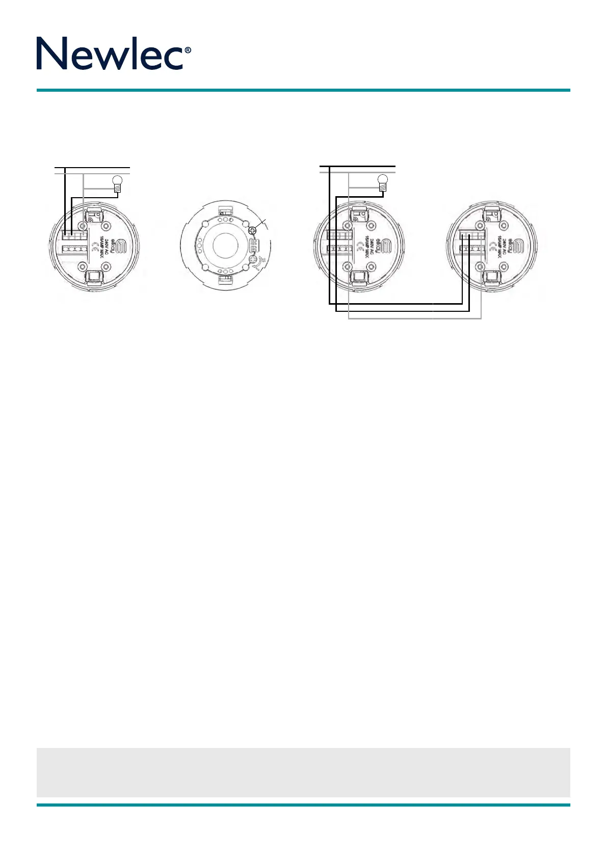
STEP 2 - Ensure that the mains power to the circuit is
switched o. Ensure terminal cover and cable cl amp are
correctly fitted with screws supplied. Place the Live In into the
Terminal marked Live In and the switched Live Out into the
Live Out terminal. Place the neutral into the connection
marked N for neutral. Please note that it is essential that
the Live In wire and the switch Live Out and Neutral are
identified prior to commencing installation. To connect
multiple units connect the live switch live and neutrals as
shown in Diagram 2. Turn o mains supply for installation
as live working is not recommended and can damage
the unit.
STEP 3 - For flush mounting fold the two arms up into the
vertical position and insert unit into the hole. Release unit
ensuring arms are securely in place. For surface mounting fit
surface mount cup onto ceiling or conduit terminal box
and
return connected PIR into surface mount cup.
STEP 4 - Remove the fascia by turning anti-clockwise to
show the lux pot, sensitivity pot and the timing/lux Dip
switches. Please adjust the Lux Level and Sensitivity
potentiometer gently without force as this is a sensitive
electronic part. After adjustment please wait 30 seconds for
changes to take eect. It is recommend product is set up
initially using the 10 secs walk test mode.
STEP 5 - To set Auto Lux (150 Lux) switch Dip switch 4 to
the ON position. This will allow activation of the PIR from
Dusk until Dawn only. To set manually then put dip switch 4
o and use the potentiometer to adjust to desired lux level
setting. All the way to the plus setting will allow the PIR to
switch day and night. All the way to the minus sets the timer
to ZERO lux and eeftively switches o the PIR. To set manually
you will need to be present at dusk. (See Diagram 3).
STEP 6 - To adjust sensitivity turn anti-clockwise to the
High (H) setting to increase sensitivity and clockwise to the
Low (L) to decrease sensitivity.
STEP 7 - To set time please utilise the dip switch timing
diagram above. The black bar denotes dip switch position.
Replace fascia ring by turning anti clockwise
(See Diagram 4).
STEP 8 - The PIR will take approximately 2½ minutes to
initialise and will flash rapidly after the mains power is first
applied to allow the sensor to learn its environment. The
load will be ON after 7 seconds initially, then switch o
after 2½ minutes if there is no detection in the zones.
OPERATION
In standard operation the PIR will now sense infra red heat
when a person or source of heat passes through the
detection zone. Each time the PIR is triggered it will reset
the timer back to the start of the timing period. The unit will
then wait 5 seconds before allowing the PIR to sense and
re trigger the timing period again.
If no one is present in the room or the detection zone is not
passed through, during its set time period, the timer will
time out, turning o the lights or appliance.
The PIR unit will only trigger the lights or appliance if the
ambient light level is below that set on the lux level
adjustment.
4.
3.
2.
1.
ON DIP
Test Mode
10 Secs
4.
3.
2.
1.
ON DIP
Auto Lux
DIAGRAM 2
DIAGRAM 4
Time Settings (Test Mode to 60 mins)
RPM 3 7 7
CEILING MOUNT (PIR)TIMER
IMPORTANT NOTICE
All wiring should be carried out by a competent person or a qualified electrician and should be fitted to IEE 17th Edition Wiri ng regulations
BS7671:2008. The circuit should be isolated before carrying out any work. Failure to adhere to the instructions will invalidate the warranty.
Instructions
Newlec Helpline: 0845 123 6539
IMPORTANT NOTICE
All wiring should be carried out by a competent person or a qualified electrician and should be fitted to IEE 17th Edition Wiri ng regulations
BS7671:2008. The circuit should be isolated before carrying out any work. Failure to adhere to the instructions will invalidate the warranty.
Newlec Helpline: 0845 123 6539
 Loading...