4
For more information visit us online www.newtonwaterproong.co.uk Call us for more information on +44 (0)1732 360095
5
The Newton Pump Controller is designed to be used with matched pairs of manual versions of Newton Pumps,
and provides a sophisticated, yet simple to install, twin pump control system which offers some of the features
of the Newton Control Panel-Pro, but at a much lower cost.
The controller has a mains powered alarm with battery backup alarm and features interfaces for use with
Newton battery backup and telemetry systems, as well as connections to whole house alarm and monitoring
systems. The major feature of the control system is the self diagnostic program that operates both pumps
on a weekly basis to ensure that they are not stood idle for extended periods, in order to prevent seizure and
premature pump failure. Each pump will operate for 5 seconds, (one after the other) once per week.
Each pump is operated by its own vertical type oat switch with a single reed type switch supplied for the alarm
system which incorporates the same PCB as the Newton PA50 Alarm unit. The panel is designed to be used with
an optional Newton Victron Power Inverter, sized to suit the pumps and installed with sufcient battery power to
ensure continued pumping during power outages.
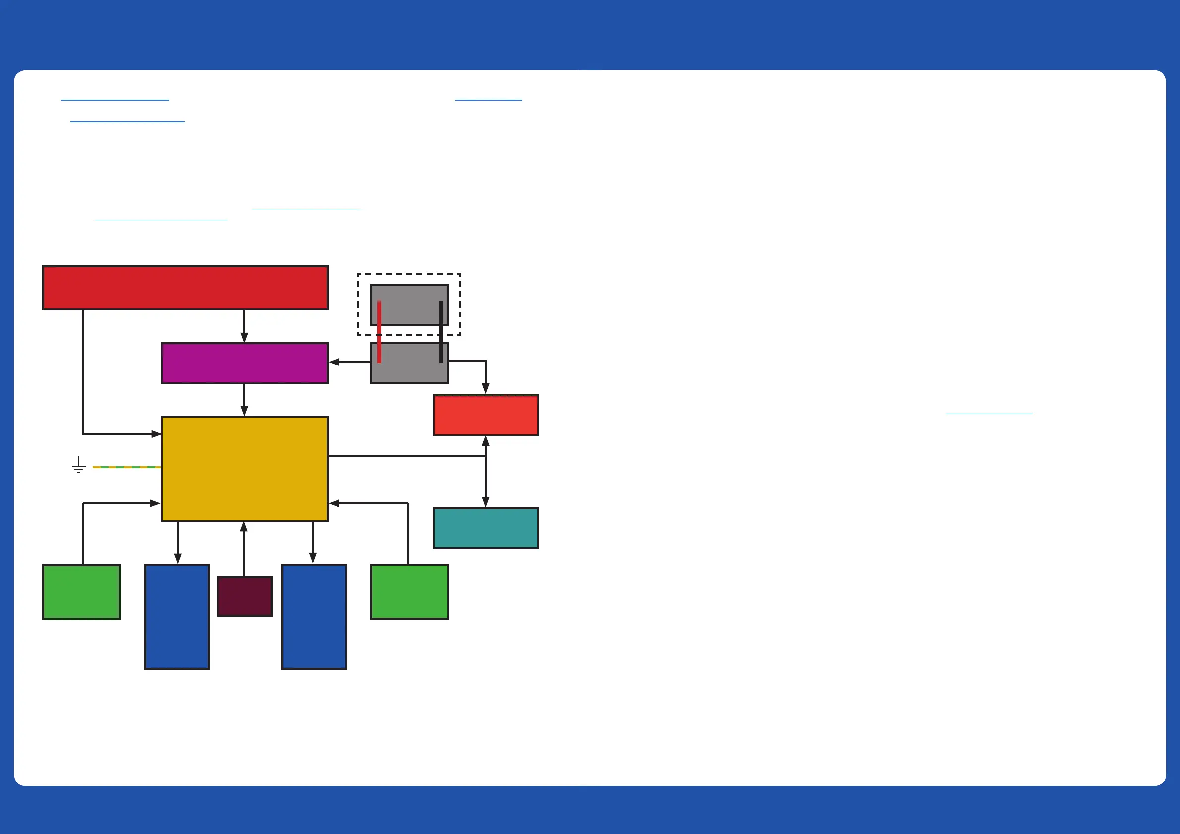
A typical system is shown below:
PANEL HIGHLIGHTS
1. Two independent power supply inputs - Each pump is separately and independently powered from the
other. The operation of the pumps is not at all dependent on the operation of the Pump Controller. If the
Pump Controller should fail, the oat switches will still have the ability to switch on the pumps as if they
were automatic pumps.
2. Automatic pump duty assist - If one pump cannot cope with the volume of water entering the sump, the
water level will rise to the switch of the second pump, which will automatically start to increase the pumping
capability. Please be aware that separate discharge lines maximises the volume of water removed when this
feature is utilised.
3. Automatic alarm oat checking - An alarm checking signal is continually monitored to conrm the alarm
oat cables have been tted correctly, not been tampered with, or been disconnected.
4. Automatic testing of each pump every 7 days - The test ensures the pumps are used each week. Each
control circuit has its own independent timer to ensure that each pump is tested at different times.
5. Test Button - Both pumps can be started from the panel for testing.
6. Alarm Power - The Alarm is powered under normal circumstances by 230V mains and by internal 9V battery
during power outage.
7. If the sounder is beeping to warn of high water level, you can mute the sounder by pressing the mute
button once. The LED will still ash until reset (in Alarm Mode 1).
8. Pump Counter - An internal, 6 digit counter is included that counts the number of times Pump 1 operates
(Not Pump 2). This count includes the weekly pump test and pump operations activated by the oat switch.
9. Choice of pumps - A choice of a number of Newton manual pumps of 250, 400 and 750 watts.
10. Battery Backup - Optional Newton Victron Power Inverter can be connected to the unit to provide
continuation of pumping (Pump 2) during power outage.
11. Fail-Safe - Telemetry - Pump Controller can be connected to the Newton Dialer (PA5) or to home alarm
system (BMS - Building Management System)
ENCLOSURE
The Pump Controller is housed in a 300 mm wide x 132 mm high x 78 mm deep, painted steel enclosure with a
minimum of 8 knockouts for tting suitable plastic cable glands or conduit connectors ready for the following
cables:
Mains Power 1; Mains Power 2; Pump Float 1; Pump Float 2; Pump 1; Pump 2; Alarm Float; Connection to Dialer.
The Pump Controller can be surface mounted or ush mounted. Please ensure the correct variant is ordered:
SURFACE MOUNTED - PURCHASE CODE CP9
Parts:
1 x Pump Controller
2 x Pump Float Switches
1 x Alarm Float Switch
2 x 32 mm Conduit Connectors
10 m 32 mm Conduit
1 x 25 mm Conduit Connectors
5 m 25 mm Conduit
FLUSH MOUNTED - PURCHASE CODE CP9F
Parts:
1 x Pump Controller
2 x Pump Float Switches
1 x Alarm Float Switch
8 x Cable Glands
1 x Flush Mount Trim
8 x Cable Glands
Fix the enclosure to the wall or within the wall using xings that are suitable for the weight of the unit and your
wall type. The face plate is attached to the back-box and supplied with M3 ange combi screws and plastic
washers.
Newton Pump
Controller
Grid mains power supply 230V AC 13A
Pump
Float
Pump
Float
Manual
Newton
Pump
400 to
750W
Manual
Newton
Pump
400 to
750W
Power Inverter
(option)
Battery
Battery
OPTIONAL
BATTERY(S)
Dialer
PA5 - (Option)
House Alarm
(option)
Alarm
Float
INTRODUCTION DESCRIPTION OF FEATURES
 Loading...