6
For more information visit us online www.newtonwaterproong.co.uk Call us for more information on +44 (0)1732 360095
7
ELECTRICAL CONNECTION
INSTALLATION WARNINGS:
THIS CONTROL PANEL MUST ONLY BE INSTALLED BY TRAINED ENGINEERS.
BEFORE COMMENCING INSTALLATION, ISOLATE YOUR MAINS ELECTRIC SUPPLY.
This product should be installed in accordance with the relevant sections of the building regulations code and the
current edition of the IEE Wiring Regulations (BS 7671: Requirements for electrical installations) and appropriate
statutory regulations.
As of April 2004, new installations in the UK should be wired using the EU harmonised colours for the supply
conductors. NEW COLOURS: BROWN = Live, BLUE = Neutral, YELLOW / GREEN = Earth. This installation MUST be
earthed.
This control panel is not waterproof, is of metal construction and must be installed in a dry, well ventilated area.
Warning: it is important to read and understand the Pump Controller instructions
This Newton Pump Controller has been designed to be wall mounted or recessed within the wall. When the
unit is recessed into the wall, the routing of all cables is also within the wall, making a neater installation than if
the unit is wall mounted. Cable entry is via the knock-outs to the bottom and side of the panel, and glands are
supplied for recessed mounting.
For ease of maintenance in changing pumps, it is recommended to always use 1 x 32 mm conduit for the two
pumps, 1 x 32 mm conduit for the two oat cables and 1 x 25 mm conduit for the Alarm Float Cable.
For surface mounting, the panel looks neater if the 32 mm and 25 mm conduits are tted directly to the unit.
NOTES:
The two supplied vertical oats, when connected to the unit, are high-voltage. Please note that low-voltage
rated cables cannot be run in the same conduit as high-voltage (230V AC) cables. The Panel must be earthed.
If the sump chamber is full of water on rst powering up the panel, the alarm may sound and both pumps may
start together. When the water level is below the alarm oat, the alarm sounder will cease and the remainder of
the water will be removed by Pump 1.
CONNECTIONS
Mains 1 - 230V AC supply suitably rated to operate Pump 1 from a locally fused spur, preferably from its own
feed off the consumer board.
Mains 2 - 230V AC supply suitably rated to operate Pump 2 from a locally fused spur, preferably from its own
feed off the consumer board OR 230V AC power supply from a correctly sized Newton Power Converter (see
page 10 for information on Power Converter sizing).
Float 1 - Connections to 230V AC vertical type oat switch.
Float 2 - Connections to 230V AC vertical type oat switch.
Pump 1 - 230V AC output to Pump 1.
Pump 2 - 230V AC output to Pump 2.
Dialer - Volt free relay contact which operates upon alarm, sending a signal to ancillary alarm options such as
the Newton Dialer PA5 or BMS. Use NO (Normally Open) and C (Common).
Float Alarm - For connection of High Water Alarm oat.
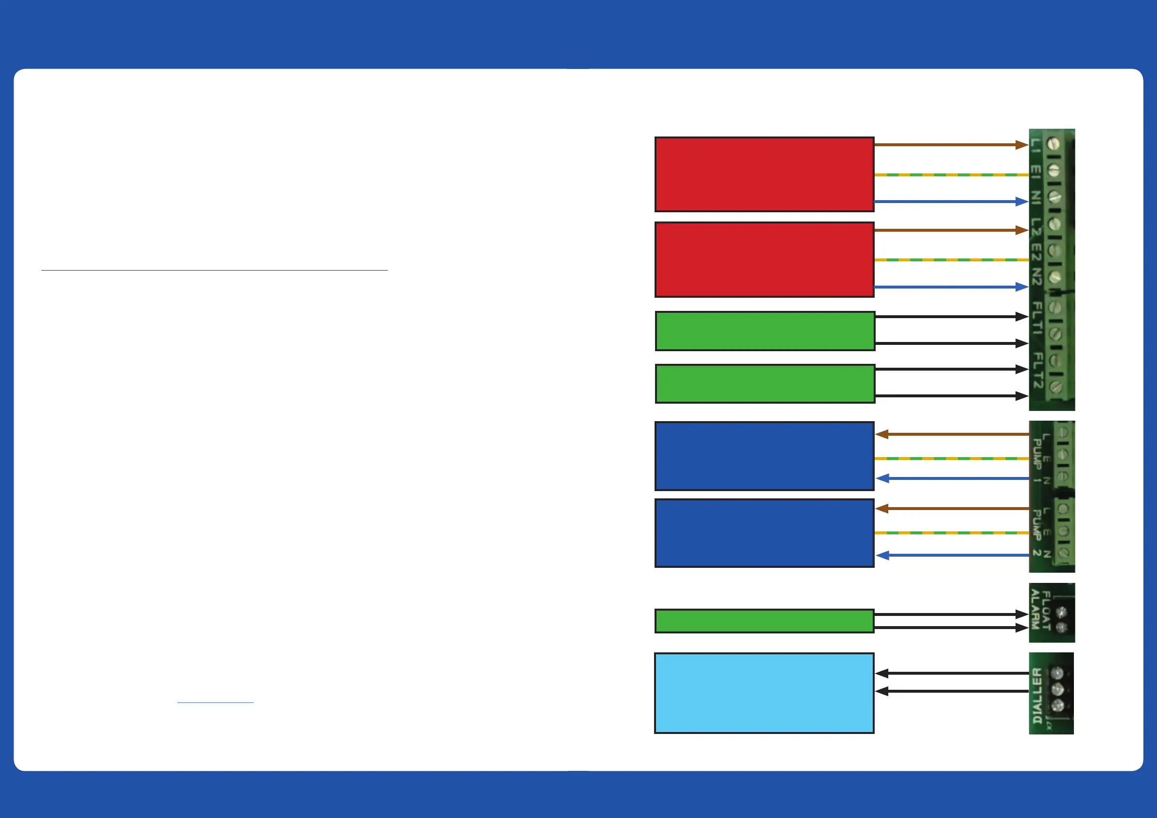
CONNECTION WIRING DIAGRAM
PUMP 1
GRID MAINS INPUT
230V AC
ALARM FLOAT (low voltage)
PUMP 1 FLOAT (mains voltage)
PUMP ONE MAINS
OUTPUT 230V AC
NEWTON DIALER (PA5)
or HOUSE ALARM SYSTEM (BMS)
(Option)
PUMP 2
GRID MAINS INPUT
230V AC
PUMP 2 FLOAT (mains voltage)
PUMP TWO MAINS
OUTPUT 230V AC
CONNECTING POWER, PUMPS & OPTIONAL EQUIPMENT CONNECTING POWER, PUMPS & OPTIONAL EQUIPMENT
 Loading...